Fuse vs Breaker Selection for Control Panels
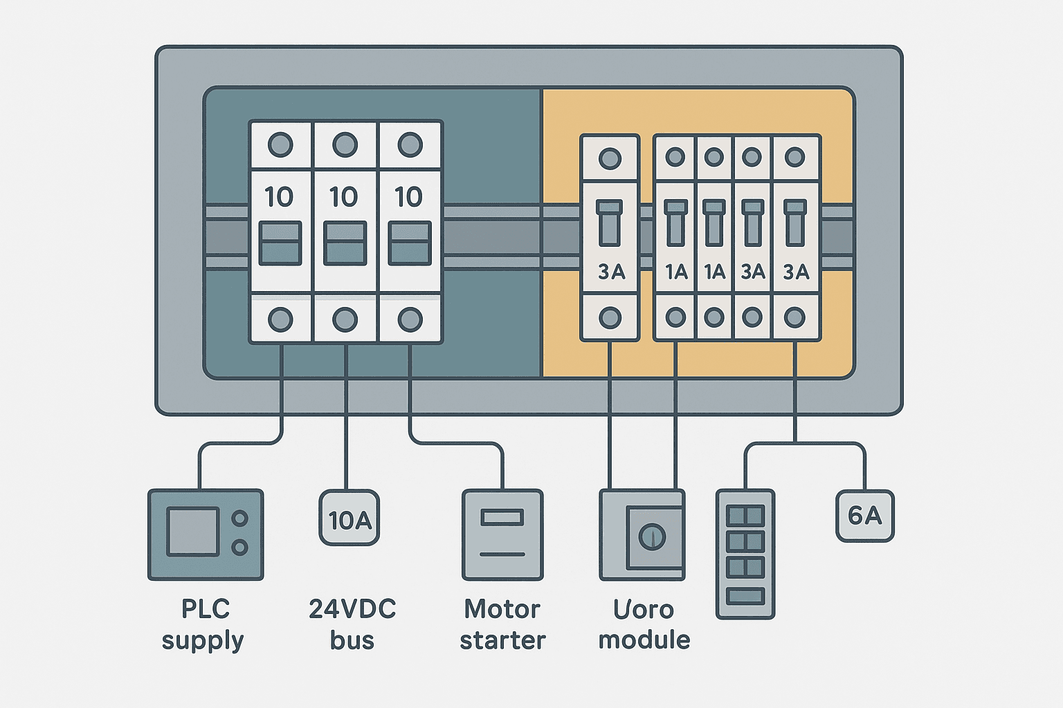
Every circuit in a control panel needs overcurrent protection. Pick the wrong device and you get nuisance trips, uncleared faults, or worse, a fire. The choice between a fuse and a miniature circuit breaker (MCB) isn't arbitrary, and it's not just about cost. It comes down to the specific fault-clearing requirements, the available short-circuit current, the load type, and how your devices need to coordinate with each other.
Fuse and Breaker Selection: The Core Trade-offs
Fuses and breakers both interrupt overcurrent, but they do it differently and they have genuinely different strengths. A fuse is a single-use sacrificial element. It clears a fault extremely fast, typically in half a cycle or less at high fault currents, and its current-limiting action can protect downstream equipment that a breaker would expose to a longer-duration fault arc. A breaker is reusable, resettable, and easier to reset after a nuisance trip, but it has a finite interrupting rating and a slower clearing time than an equivalent current-limiting fuse.
In practice I reach for fuses in two situations: high available fault current (where a breaker's interrupting rating might fall short) and protection of semiconductor-based loads like VFD input stages, where the fast clearing is essential. Breakers go everywhere else where reset convenience matters and the fault current is manageable.
Step 1: Know Your Available Short-Circuit Current
Before you specify a single device, you need the prospective short-circuit current (PSCC) at the panel's supply terminals. This is the maximum fault current the upstream supply can deliver before any protection operates. Your panel's transformer nameplate and impedance percentage give you a starting point. A 10 kVA, 230 V, 4% impedance transformer gives roughly 10,000 / (230 x 0.04) = 1,087 A prospective short-circuit current at the secondary terminals. A 75 kVA unit at the same impedance delivers about 8,150 A. For anything fed off a large distribution board with low cable impedance, measured values can exceed 25 kA.
Step 2: Match the Tripping Curve to the Load
For breakers, the tripping characteristic is the most commonly misapplied parameter. IEC 60898 and EN 60947 define several curves. The three you'll use in control panels are B, C, and D.
| Curve | Instantaneous Trip | Typical Load |
|---|---|---|
| B | 3x to 5x rated current | Resistive loads, long cable runs, sensitive electronics |
| C | 5x to 10x rated current | General purpose, small motors, transformers, solenoids |
| D | 10x to 20x rated current | High-inrush loads: large transformers, motor DOL starts, welders |
A PLC power supply drawing 3 A steady-state with no meaningful inrush works fine on a B-curve 4 A breaker. A 230 V primary control transformer that pulls 8x its rated current for the first few cycles on energisation needs a C or D curve, or it will trip every time you close the panel door. I've seen panels with 10 A C-curve breakers on the main transformer and then B-curve devices for each 24 VDC branch on the secondary side. That layering is intentional: the downstream B-curve trips first on a branch fault, leaving the main breaker intact.
Step 3: Size the Continuous Current Rating
The continuous current rating must be at least 125% of the full-load current for resistive loads, and IEC 60364 generally requires that the device rating doesn't exceed the cable's current-carrying capacity (CCC) so the cable is always the weaker link, not the protection device. Here's a practical sizing sequence:
- Calculate or measure the full-load current of the circuit.
- Multiply by 1.25 for continuous loads (NEC) or apply IEC 60364-4-43 demand factor.
- Round up to the next standard device rating (1, 2, 4, 6, 10, 13, 16, 20, 25, 32, 40, 50, 63 A are common IEC sizes).
- Check that the selected rating is less than or equal to the cable CCC from your derating tables (ambient temperature, grouping, conduit fill all reduce CCC).
- Confirm the device's interrupting rating exceeds the PSCC at that point.
Fuse Selection: Types and Where Each Fits
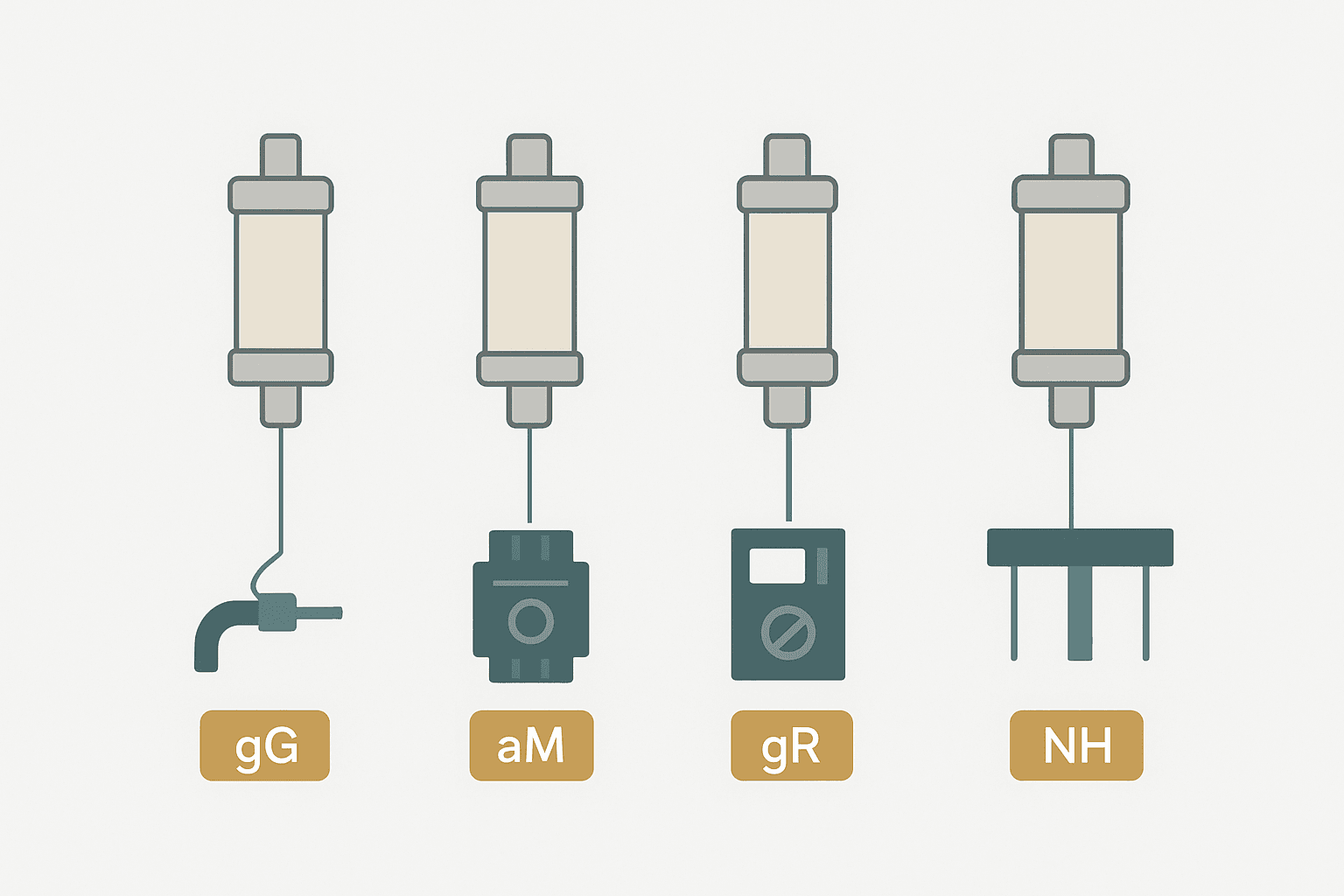
Not all fuses are created equal. In industrial panels you'll encounter several IEC fuse types:
- gG (general purpose): Protects cables and general loads. Slow enough to ride through motor start inrush. Standard choice for control circuit branch protection.
- aM (motor circuit): Designed only for overload protection in motor branch circuits when used with a contactor and overload relay. Does NOT protect against sustained overloads below its minimum breaking current: you still need the thermal overload relay.
- gR / gS (semiconductor): Very fast clearing, current-limiting fuses specifically for protecting rectifiers, VFD input bridges, and IGBT modules. Eaton Bussmann FWP series, Mersen A70QS series are examples. These are expensive but the VFD is more expensive.
- Blade/ATO fuses: Used occasionally in smaller 24 VDC distribution in tight spaces but not typical for DIN-rail panels.
- NH fuse links (DIN 43620): High-current main fusegear, common in European distribution boards feeding larger panels. Sizes from 63 A up to 1,250 A.
Coordination: Making Protection Devices Work as a System
Selectivity (also called discrimination) means that only the device closest to a fault operates, leaving everything upstream energised. This is not automatic; you have to design it in. A common failure mode is a panel where a downstream 6 A breaker fault trips the 40 A upstream breaker because both operate in the instantaneous zone at the available fault current.
The simplest rule of thumb for current discrimination: the upstream device's instantaneous trip threshold must be higher than the maximum fault current the downstream device sees. In practice that means a ratio of at least 2:1 in continuous ratings between cascaded breakers, or using time-delayed upstream devices. Manufacturer selectivity tables (Schneider Electric, ABB, and Eaton all publish these for their ranges) show you the exact upstream/downstream pairs that achieve full discrimination at your fault level. Don't guess: use the table.
24 VDC Distribution: A Specific Gotcha
DC circuits are harder to interrupt than AC circuits because there's no natural current zero crossing. A breaker rated 10 kA at 230 VAC may only be rated 5 kA at 60 VDC, and many standard MCBs are not rated for 24 VDC at all. Check the DC voltage rating on the datasheet explicitly. Phoenix Contact, Weidmuller, and E-T-A all make DIN-rail breakers and electronic circuit protectors specifically designed for 24 VDC distribution. The E-T-A 3120 series and Phoenix Contact CB-E series are devices I've used successfully on tight 24 VDC branches where per-channel protection was needed without pulling a fuse every time a sensor shorted.
Electronic circuit protectors (sometimes called solid-state breakers) are worth knowing about for 24 VDC. They use a MOSFET to limit current instantly, they're resettable remotely, and some give you diagnostic current readings via IO-Link. They cost more than a fuse holder but they save a lot of troubleshooting time when a field device develops an intermittent short.
Motor Branch Circuits: Breaker, Fuse, or Both?
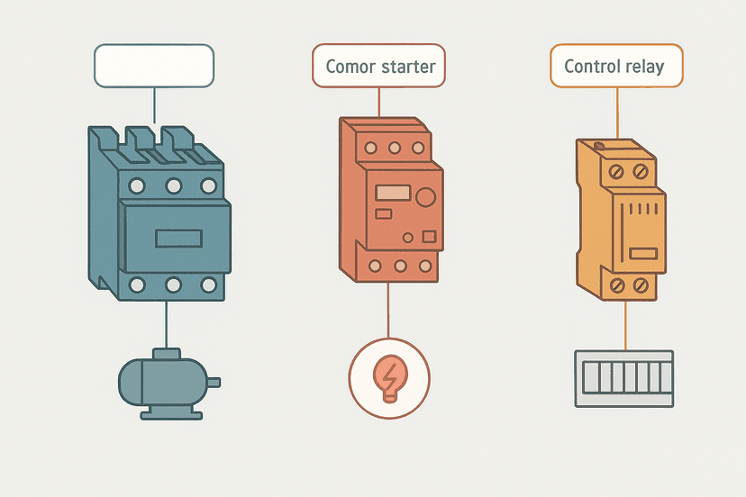
A motor branch circuit in IEC practice typically uses a combination of: a motor circuit breaker (MCB with magnetic-only trip and motor starting characteristic, like a Siemens 3RV2 or Eaton PKZM0) for short-circuit protection and manual isolation, plus a thermal overload relay in the contactor for sustained overload protection. This is your Type 2 coordination combination if you pick matching pairs from the manufacturer's tables. Type 2 means that under a short-circuit condition neither the contactor nor overload relay are damaged to the point of being unusable.
For higher-power motors or when the available fault current exceeds the MCB's rating, you drop in gG or aM fuses for short-circuit protection and keep the thermal overload relay for sustained overload. The fuse handles the catastrophic event; the relay handles the slow cook.
Quick Selection Reference
| Circuit Type | Recommended Device | Key Parameters to Check |
|---|---|---|
| PLC / SMPS power supply | B-curve MCB, 125% of rated input current | DC voltage rating if on 24 V rail; interrupting capacity |
| 24 VDC sensor branch | DIN-rail DC breaker or electronic circuit protector | Voltage rating for DC; per-channel current limit |
| Control transformer primary | C or D-curve MCB, sized to primary FLA x 1.25 | Inrush withstand; interrupting capacity at supply fault level |
| Small motor (DOL, <7.5 kW) | Motor circuit breaker (3RV2, PKZM0) + thermal overload | Type 2 coordination pair; Ir setting to motor FLA |
| VFD input | gR or gS semiconductor fuse | I2t rating; current-limiting class; fuse size from VFD manual |
| General 230 VAC branch | C-curve MCB, next size above 125% FLA | Cable CCC; interrupting rating vs PSCC |
Documentation You Actually Need
Every panel should have a circuit schedule that lists each protective device, its rating, its curve or fuse type, the cable size it protects, and the load it feeds. This isn't just good engineering practice; it's what the next technician needs at 2 AM when something trips. I've audited panels with no labeling and no schedule, and tracking down a nuisance trip through 30 identical breakers in an unlabeled panel is miserable. Label the devices, number the terminals, and keep the schedule in the panel door pocket.
Frequently asked questions
When should I use a fuse instead of a circuit breaker in a control panel?
What is the difference between a B, C, and D curve circuit breaker?
Can I use a standard AC circuit breaker to protect a 24 VDC circuit?
What is selectivity (discrimination) and why does it matter?
What fuse type should I use to protect a VFD?
How do I calculate the prospective short-circuit current at my panel?
Learn this by building it
There is a PLC in this site. It runs a real scan engine, checks your logic against the same tests a working machine would fail, and needs no download and no account.
Open the exercisesFree, no signup, runs in your browser. See all 16 exercises.
Was this helpful?