IEC 62061 PFHd Calculation: A Step-by-Step Guide
Once you have read up on what SIL levels mean, the next question is always the same: how do you actually prove your design hits the target? That proof lives in a single number called PFHd (Probability of Dangerous Failure per Hour). It is the metric IEC 62061 uses to assign a Safety Integrity Level to a Safety Instrumented Function (SIF), and getting it wrong means either a system that is dangerous or one that is needlessly over-engineered.
This post walks through the PFHd calculation method defined in IEC 62061:2021, using a realistic E-stop SIF on a press as the worked example. No hand-waving, no skipping steps.
What PFHd Actually Represents
PFHd is the average frequency at which a safety function fails to operate on demand in a dangerous, undetected way. The unit is failures per hour. Think of it as the rate at which your E-stop quietly breaks without anyone noticing. A lower number is safer.
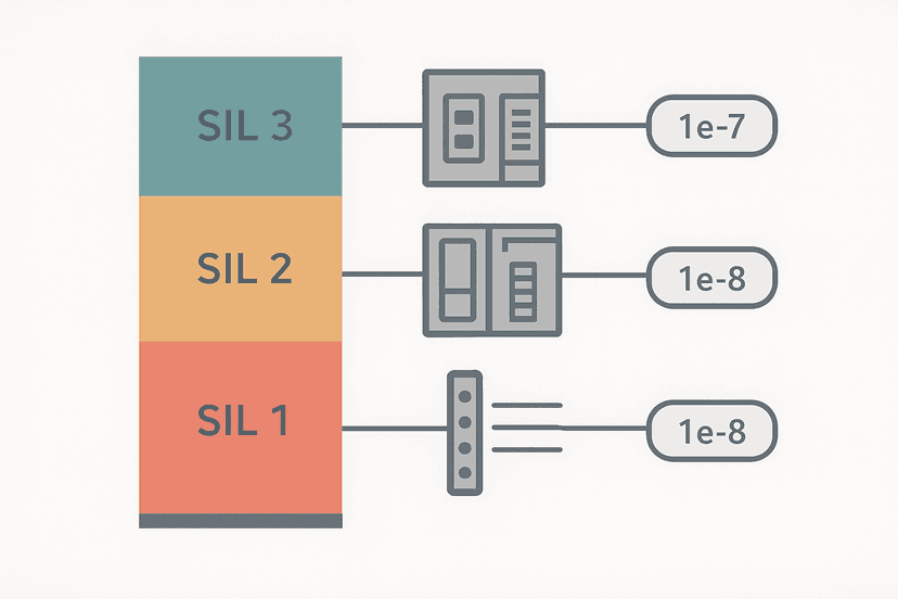
| SIL | PFHd range (1/h) | Typical application |
|---|---|---|
| SIL 1 | 1e-5 to <1e-4 | Low-risk process guarding |
| SIL 2 | 1e-6 to <1e-5 | Press E-stop, robot safeguard |
| SIL 3 | 1e-7 to <1e-6 | Burner management, overpressure |
The Three-Subsystem Architecture
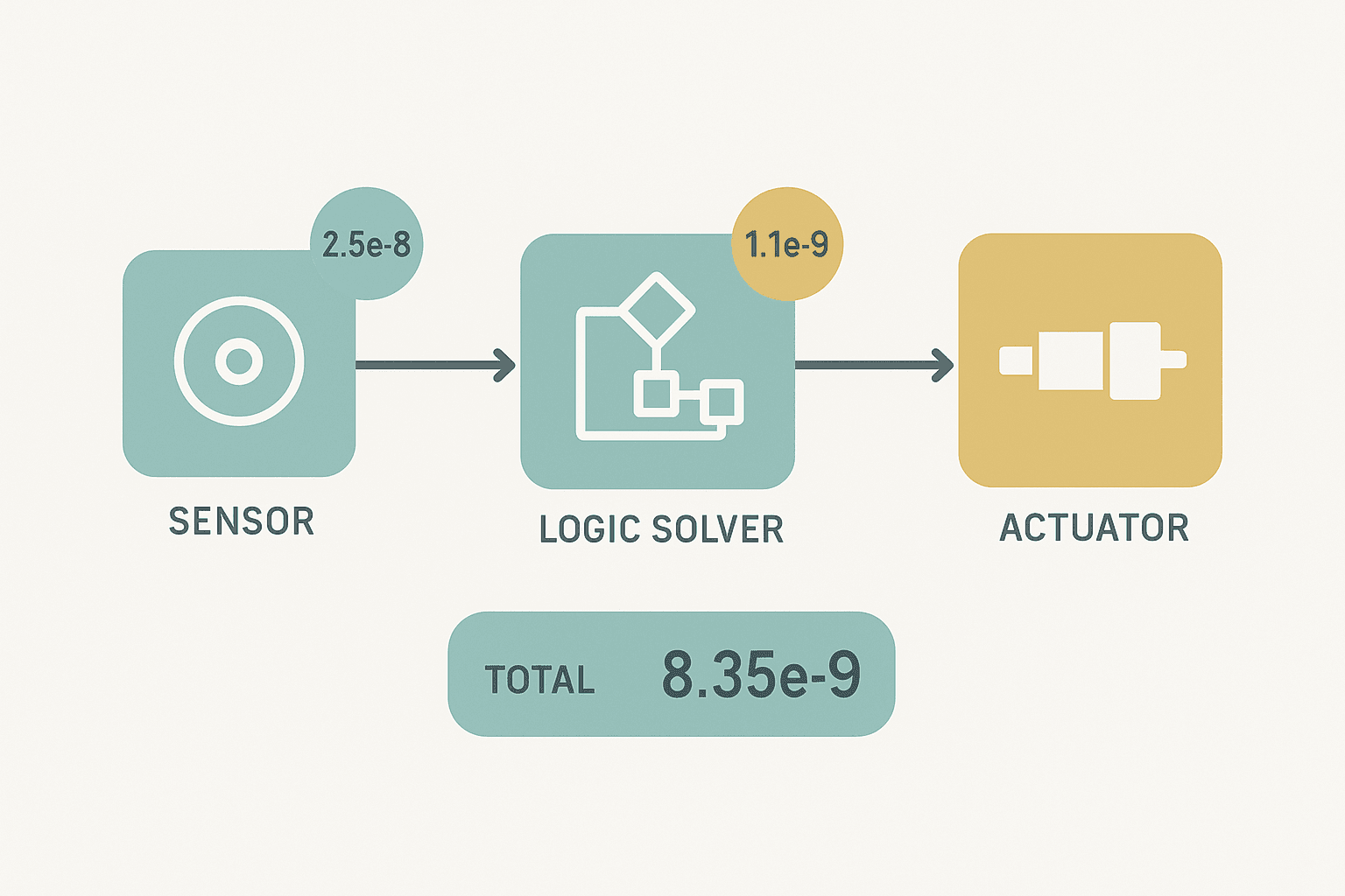
IEC 62061 treats every SIF as a chain of three subsystems: Input (I), Logic Solver (L), and Output (O). You calculate a PFHd for each subsystem separately, then add them.
Total PFHd of the SIF = PFHd(I) + PFHd(L) + PFHd(O)
That additive property is only valid when the subsystems are independent, which they usually are in a well-designed panel. If they share a power supply or a common cable duct, you have a common cause issue that needs separate treatment under Annex F of the standard.
Key Input Data You Need Before You Start
For each component in each subsystem you need:
- lambda (failure rate, 1/h): from the component supplier's safety manual or a generic database like SN 29500 or IEC 62061 Annex D.
- Beta (common cause failure fraction): the proportion of failures that hit all redundant channels simultaneously. Typical values are 1% to 5% depending on your separation measures.
- DC (Diagnostic Coverage): the fraction of dangerous failures detected by built-in diagnostics. Expressed as a decimal (0.99 = 99%).
- Architecture (HFT): Hardware Fault Tolerance. HFT 0 = single channel, HFT 1 = 1oo2 or 2oo3, etc.
- T1 (proof-test interval): how often you manually verify the safety function works end-to-end. Commonly 1 year = 8760 h.
PFHd Calculation for IEC 62061 Architecture A (HFT 0, Single Channel)
For a single-channel subsystem (HFT = 0) the IEC 62061 formula from Table D.1 simplifies to:
PFHd = lambda_de * T1/2 + lambda_du * T1
Where:
lambda_de= detected dangerous failure rate = lambda_d * DClambda_du= undetected dangerous failure rate = lambda_d * (1 - DC)T1= proof-test interval in hours
The T1/2 factor on the detected term comes from the assumption that on average a detected failure is caught halfway through the interval. The undetected failures persist the full interval, so they get T1 (actually a slightly more complex integral, but T1 is the conservative approximation the standard allows for lambda_du * T1 < 0.1).
Worked Example: SIL 2 E-Stop on a Mechanical Press
Target SIF: pressing an E-stop mushroom-head removes power to the press clutch via a safety relay, stopping the ram. Target SIL = 2, so total PFHd must be below 1e-6 /h.
Input Subsystem: Dual-Channel E-Stop Button
We are using a Schmersal TK 400 E-stop with two forced-guided NC contacts wired to two separate input channels of a safety relay. This is HFT = 1 (2-channel, 1oo2 voting).
From the Schmersal safety manual: lambda_d = 1.6e-8 /h per contact. DC = 99% (cross-fault monitoring by the safety relay). Beta = 2% (separate conduits, different cable colours).
For 1oo2 with HFT = 1, IEC 62061 Table D.1 gives:
PFHd(I) = (1-Beta) * lambda_de^2 * T1^2 / 2 + Beta * lambda_du * T1 + Beta * lambda_de * T1/2
Plugging in numbers (T1 = 8760 h, DC = 0.99):
- lambda_de = 1.6e-8 * 0.99 = 1.584e-8 /h
- lambda_du = 1.6e-8 * 0.01 = 1.6e-10 /h
- (1-Beta) * lambda_de^2 * T1^2 / 2 = 0.98 * (1.584e-8)^2 * 8760^2 / 2 = approximately 8.3e-11
- Beta * lambda_du * T1 = 0.02 * 1.6e-10 * 8760 = 2.8e-11
- Beta * lambda_de * T1/2 = 0.02 * 1.584e-8 * 8760/2 = 1.39e-6
PFHd(I) = approximately 1.4e-6 /h. That single term already threatens the SIL 2 budget. The culprit is Beta. A 2% common cause fraction with a 1-year proof test pushes the CCF term to 1.39e-6 all by itself. This is the number one lesson from real SIL 2 E-stop calculations: Beta dominates.
Logic Solver Subsystem: Pilz PNOZ m B0 Safety Relay
The Pilz PNOZ m B0 module is a certified safety relay with a published PFHd of 8.4e-10 /h (from the Pilz safety manual, valid for T1 = 8760 h). You do not calculate this one from scratch: you take the figure directly from the manufacturer's safety manual.
PFHd(L) = 8.4e-10 /h
Output Subsystem: Single Contactor Dropping Clutch Power
The output is a single 24 V DC contactor (HFT = 0) with no redundancy. From SN 29500 and the supplier's safety manual, lambda_d = 1.0e-7 /h, DC = 0 (no diagnostics on the contactor itself).
Single channel, DC = 0, so lambda_de = 0 and lambda_du = 1.0e-7 /h.
PFHd(O) = lambda_du * T1 = 1.0e-7 * 8760 = 8.76e-4
That is catastrophic. An undiagnosed single contactor with a 1-year proof test is nowhere near SIL 2. You need either a second contactor in series (HFT = 1) or a contactor with guided contacts and mirroring feedback to the safety relay to get DC up to at least 90%.
Switching to two contactors in series with mirror-contact feedback (DC = 99%, Beta = 2%, lambda_d = 1.0e-7 /h each):
Applying the same 1oo2 formula: PFHd(O) calculates to approximately 2.0e-9 /h. Now the output is not the problem.
Summing the SIF
| Subsystem | Architecture | PFHd (1/h) |
|---|---|---|
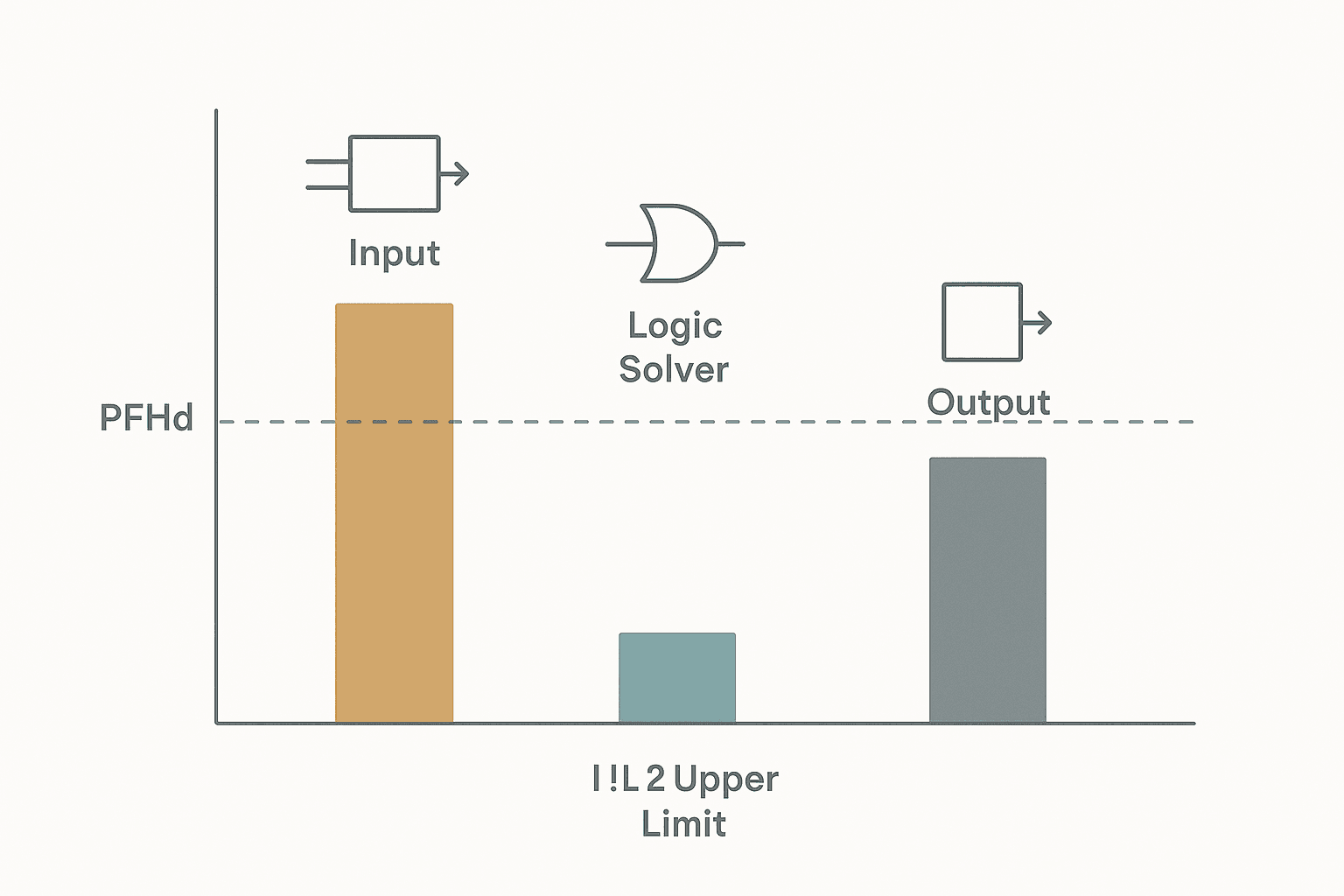
| Input (dual E-stop, Beta=2%, T1=8760h) | HFT 1 | 1.4e-6 |
| Logic solver (Pilz PNOZ m B0) | Internal 1oo2 | 8.4e-10 |
| Output (2 contactors in series, DC=99%) | HFT 1 | 2.0e-9 |
| **Total SIF** | **~1.4e-6** |
At 1.4e-6, this design sits in SIL 1 territory. To hit SIL 2 you have two practical options: reduce Beta to 1% by fully separating the input channels, or halve the proof-test interval to 4380 h (6 months). Halving T1 drops the CCF term proportionally, bringing PFHd(I) down to around 7e-7 and the total SIF to about 7e-7, which is safely inside SIL 2.
PFHd Calculation: Common Mistakes in the Field
- Using MTBF instead of lambda_d. MTBF from a generic datasheet covers all failure modes, safe and dangerous. Divide by 2 as an absolute minimum, or better, get the real dangerous failure rate from the safety manual.
- Ignoring Beta. A lot of engineers skip Beta because it is awkward to quantify. As the numbers above show, it often dominates the result.
- Setting T1 to the machine service life. The proof-test interval is the functional test frequency, not the design life. If your safety procedure says 'test annually', T1 = 8760 h.
- Treating the safety relay as zero PFHd. Every certified device has a published PFHd. Add it in, even if it is small.
- Forgetting the output subsystem. A single unmonitored contactor will blow any SIL 2 budget instantly.
Software Tools and Documentation
You can do the arithmetic in a spreadsheet, but a few commercial tools automate the subsystem formulas and generate the required IEC 62061 Clause 8 documentation: Sistema (free, from BGIA/IFA in Germany) is the most widely used in machinery. Pilz PAScal and Sick Safety Designer also work well and link directly to their own component databases. Whichever tool you pick, you still need to supply the correct lambda_d, DC, Beta and T1 values yourself. The tool does not validate your inputs.
What to Do After the Calculation
The PFHd number is necessary but not sufficient. IEC 62061 also requires you to verify architectural constraints (the Hardware Fault Tolerance table in Clause 6.7), confirm that the SIL capability of each subsystem meets the target, and write a functional safety plan with the proof-test procedures that justify your chosen T1. The calculation is part of a body of evidence, not a standalone pass/fail stamp.
If you are new to building that body of evidence, start with a simple single-SIF machine, do the PFHd calculation by hand once before trusting any software tool, and get the design reviewed by a functional safety engineer. The numbers are not hard once you have done one end-to-end. The hard part is knowing which component data to trust.
Was this helpful?