Modbus RTU Protocol Explained: Frames, Timing and Wiring
Modbus RTU is pushing 50 years old and it is still the protocol you will find on the majority of drives, meters, and sensors on any given plant floor. Not because it is fancy, but because it is simple, it runs on cheap RS-485 wiring, and every vendor supports it. If you have spent any time chasing a slave that randomly stops responding, or scratching your head over byte-swapped register values, this post is for you.
What Modbus RTU Actually Is
Modbus RTU (Remote Terminal Unit) is a serial communication protocol defined in the Modbus specification published by Modbus.org. RTU is one of three transmission modes: RTU, ASCII, and TCP. RTU is the most common serial variant. It encodes data as raw binary bytes, which makes it compact and fast compared to ASCII mode, which wastes bandwidth turning every byte into two hex characters.
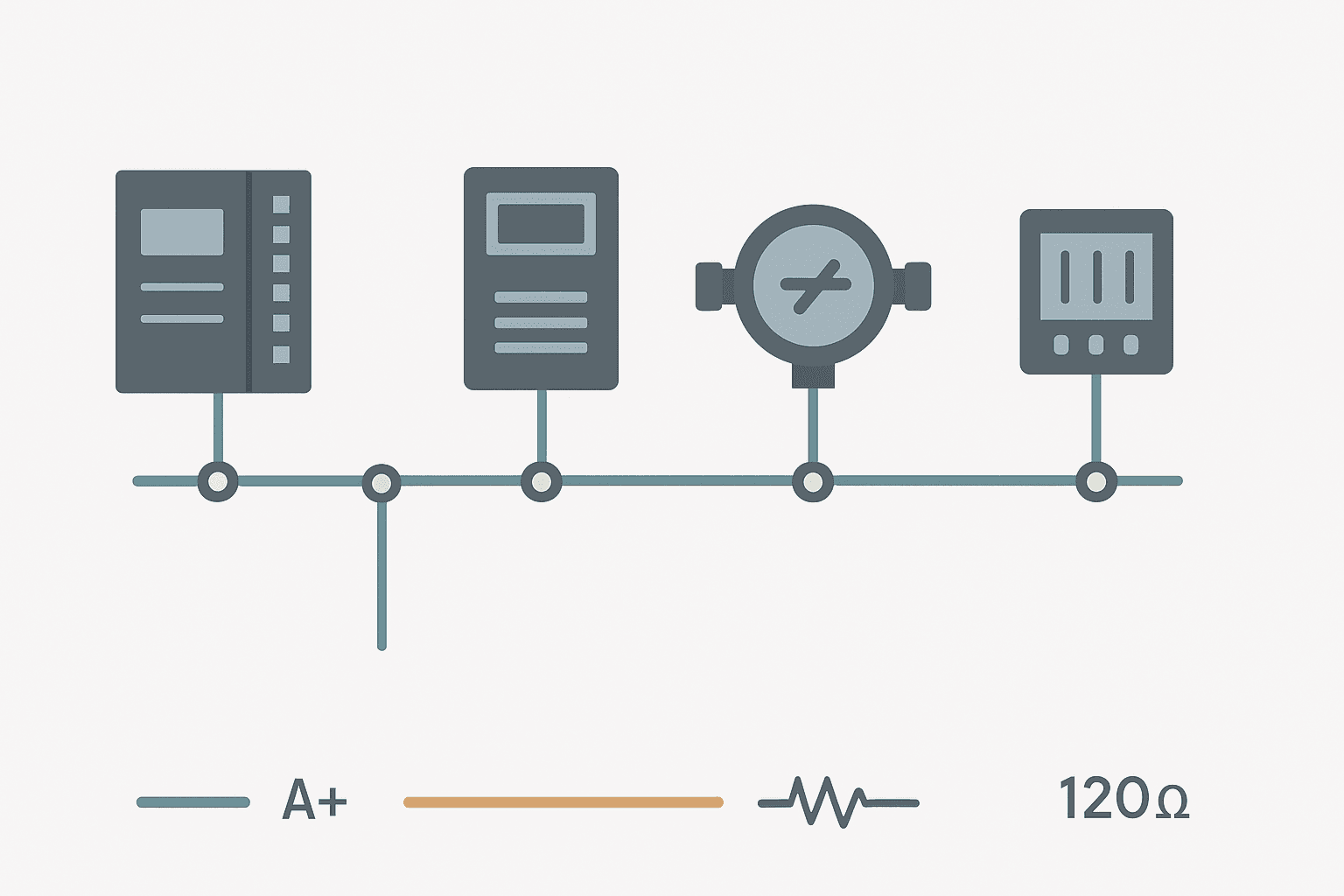
The physical layer is almost always RS-485, though you will occasionally see RS-232 for a single point-to-point link. RS-485 is a differential signalling standard: it uses two wires (A and B, sometimes labelled D+ and D-) and can support up to 32 standard unit loads on one bus, which in practice means 30 to 32 slave devices before you need a repeater. Maximum cable length is commonly quoted at 1200 m at 9600 baud, though at 115200 baud you will start losing signal integrity beyond roughly 100 to 150 m.
Modbus RTU Frame Structure
Every Modbus RTU transaction is a request from the master followed by a response from the slave. There is always exactly one master on the bus. Slaves never transmit unsolicited. A frame looks like this:
| Field | Size (bytes) | Notes |
|---|---|---|
| Slave Address | 1 | 1 to 247; 0 is broadcast (no response) |
| Function Code | 1 | 01, 02, 03, 04, 05, 06, 15, 16 are the common ones |
| Data | 0 to 252 | Register address, quantity, and values depending on FC |
| CRC | 2 | CRC-16 (polynomial 0x8005), low byte first |
The CRC is calculated over everything before it: address, function code, and data. The low byte of the CRC goes on the wire first. This trips up a lot of people who implement it by hand because the Modbus spec says low-byte-first but the surrounding data fields are big-endian (high byte first). That inconsistency has caused more head-scratching than almost anything else in Modbus.
The Common Function Codes
| FC (hex) | FC (dec) | Operation | Data type |
|---|---|---|---|
| 0x01 | 1 | Read Coils | 1-bit outputs (read/write) |
| 0x02 | 2 | Read Discrete Inputs | 1-bit inputs (read only) |
| 0x03 | 3 | Read Holding Registers | 16-bit read/write registers |
| 0x04 | 4 | Read Input Registers | 16-bit read-only registers |
| 0x05 | 5 | Write Single Coil | 0x0000 = OFF, 0xFF00 = ON |
| 0x06 | 6 | Write Single Register | 16-bit value |
| 0x0F | 15 | Write Multiple Coils | Multiple 1-bit outputs |
| 0x10 | 16 | Write Multiple Registers | Multiple 16-bit values |
FC03 (read holding registers) is what you will use 80% of the time. Your VFD output frequency, your flow meter total, your temperature transmitter scaled value: all sitting in holding registers, all read with FC03. FC04 (read input registers) is physically identical in frame structure but targets a different address space. Many devices map everything into holding registers and ignore FC04 entirely, which the spec allows.
A Real FC03 Request and Response
Say you want to read 2 holding registers starting at address 40001 (Modbus PDU address 0x0000) from slave 3. The raw bytes on the wire look like this:
Request (master -> slave):
  03        Slave address
  03        Function code (Read Holding Registers)
  00 00     Starting register address (0x0000 = register 40001)
  00 02     Quantity of registers to read (2)
  C4 0B     CRC-16 (low byte first)

Response (slave -> master):
  03        Slave address (echo)
  03        Function code (echo)
  04        Byte count (2 registers x 2 bytes = 4)
  01 F4     Register 40001 value = 0x01F4 = 500 decimal
  00 0A     Register 40002 value = 0x000A = 10 decimal
  51 78     CRC-16 (low byte first)
Notice the off-by-one that catches everyone at least once: the Modbus specification address space starts at 0. Register 40001 in the 5-digit convention maps to PDU address 0x0000. Register 40010 maps to PDU address 0x0009. Your PLC driver, your HMI, your SCADA package: they may add 1 or they may not. Always check the vendor's documentation to confirm whether their tool expects 0-based or 1-based addressing. The Modbus register calculator on this site can help you decode raw register bytes and sort out byte/word order before you even touch the PLC.
Timing: Silent Intervals and the 3.5-Character Rule
Modbus RTU has no start/stop delimiter bytes. Instead, a message boundary is defined by silence on the bus. The spec says a gap of 3.5 character times between bytes signals the end of one frame and the start of a new one. At 9600 baud, one character (1 start bit + 8 data bits + 1 stop bit = 10 bits) takes about 1.04 ms, so 3.5 characters is roughly 3.6 ms of silence.
| Baud Rate | 1 Character Time | 3.5-Character Gap (min silence) |
|---|---|---|
| 9600 | 1.042 ms | 3.65 ms |
| 19200 | 0.521 ms | 1.82 ms |
| 38400 | 0.260 ms | 0.91 ms |
| 57600 | 0.174 ms | 0.61 ms |
| 115200 | 0.087 ms | 0.30 ms |
In practice, most masters add extra inter-frame delay anyway because the slave needs time to turn around its RS-485 transceiver from receive mode to transmit mode. A turnaround time of 5 to 15 ms is typical and safe. If you set your master timeout too tight, you will get spurious CRC errors or missed responses, especially on USB-to-RS485 adapters that have latency of their own.
RS-485 Wiring: The Mistakes That Will Haunt You
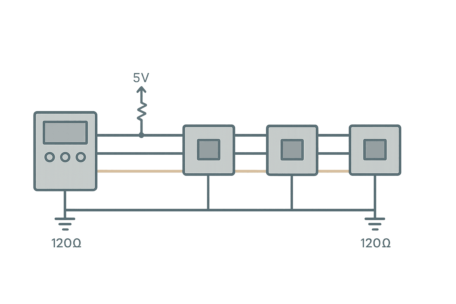
Use a daisy-chain topology, not a star. A star layout creates stubs that cause reflections and kills signal integrity above about 19200 baud. Each stub adds a reflection point.
- Termination resistors (120 ohm): fit one at each physical end of the cable run, not at each device. If you have 10 devices, only 2 of them get a termination resistor: the first and the last.
- Bias resistors: RS-485 needs a defined idle state on the bus. Most modern master devices have built-in bias (often selectable via a DIP switch). If yours does not, add a pull-up (560 ohm to 5 V) on the A line and a pull-down (560 ohm to GND) on the B line, at the master only.
- Signal ground: RS-485 is differential but it still needs a common reference. Run a third wire for signal ground (sometimes called GND or SG). Omitting it is the single most common cause of intermittent comms failures that get worse with distance.
- Cable type: use a shielded twisted pair, 120-ohm characteristic impedance, 22 AWG to 24 AWG. Belden 3105A or equivalent. Ground the shield at one end only (typically the master/panel end) to avoid ground loops.
- Max nodes per segment: 32 standard unit loads. Most modern transceivers are 1/8 UL, so you can theoretically fit 256 on one segment. Check the datasheet for your specific transceiver.
Modbus RTU vs Modbus TCP: Which One to Use
Modbus TCP wraps the same PDU (Protocol Data Unit, which is the function code plus data portion) inside a TCP/IP packet. It drops the slave address in favour of a Unit Identifier byte and removes the CRC because TCP handles error checking at the transport layer. The register model is identical. So if you already know Modbus RTU, Modbus TCP is trivial to learn.
| Feature | Modbus RTU | Modbus TCP |
|---|---|---|
| Physical layer | RS-485 (or RS-232) | Ethernet |
| Max nodes per segment | 32 (standard UL) | Unlimited (network switches) |
| Addressing | Slave address 1-247 | IP address + Unit ID |
| Error checking | CRC-16 | TCP checksum |
| Typical baud/speed | 9600 to 115200 baud | 10/100 Mbps Ethernet |
| Typical latency | 5 to 100 ms | 1 to 10 ms |
| Cabling cost | Low (twisted pair) | Moderate (Cat5e/Cat6) |
| Best for | Field devices, sensors, drives | Plant-level integration, SCADA |
RTU is still the right choice for connecting a handful of field devices to a PLC over distances up to a few hundred metres. TCP makes more sense when you are integrating across a factory network or need to talk to multiple masters. Modbus RTU to TCP converters (gateways) like the Moxa MB3170 or ProSoft MVI series sit on the RS-485 side as a Modbus master and expose a TCP server on the Ethernet side, which is a common and practical solution when you have legacy RTU slaves and a modern Ethernet-based PLC.
Configuring Modbus RTU on a PLC: What to Match
Every Modbus RTU link requires the master and all slaves to agree on five settings. Get any one wrong and you get nothing:
- Baud rate: 9600 and 19200 are the most common defaults. 9600 is the safest choice on long cable runs.
- Data bits: almost always 8 bits. Modbus RTU requires 8. ASCII mode uses 7.
- Parity: None (most common in RTU), Even, or Odd. The stop bits change accordingly: No parity = 2 stop bits, Even or Odd parity = 1 stop bit.
- Stop bits: follows from parity as above.
- Slave address: unique per device, 1 to 247. Address 0 is broadcast.
On a Siemens S7-1200 or S7-1500 you configure RTU via the MB_COMM_LOAD and MB_MASTER function blocks in TIA Portal. On a Rockwell Micro850 or CompactLogix with a serial module (such as a 1769-ASCII or a ProSoft MVI56-MCM), configuration is done through the module properties and MSG instructions. On a Mitsubishi FX3U the built-in RS-485 port uses ADPRW or IVRD/IVWR dedicated Modbus instructions. The register address offset and whether you use 0-based or 1-based addressing differs between these platforms, so always check the vendor manual for that specific module.
Troubleshooting a Dead Modbus RTU Bus
- No response at all: check baud rate, parity, and stop bits first. Then verify A and B wiring are not swapped. Measure voltage between A and B at idle: should be +200 mV or more (A positive relative to B). If it is near 0 V, your bias resistors are missing or the bus is shorted.
- CRC errors only: usually a noise or termination problem. Check that you have exactly two 120-ohm resistors, one at each physical end. A missing terminator on a long bus at 38400 baud or higher will cause intermittent CRC failures.
- Slave responds but values look wrong: byte-swap or word-swap issue. Check the device register map for 32-bit floating point values, which span two registers. Some devices send high word first, others send low word first. The Modbus register calculator can help decode these.
- Only works when cable is short: missing signal ground or bad shield termination. Add the third wire.
- Works then drops after a few minutes: check for 60 Hz or switching power supply noise coupling into the cable. Re-route away from VFD cables and power wiring, or use a different cable path.
Frequently asked questions
What is the maximum number of devices on a Modbus RTU RS-485 network?
What is the difference between Modbus RTU and Modbus ASCII?
Why do I get different values depending on which Modbus software tool I use?
Do I need termination resistors on a short Modbus RS-485 cable?
What baud rate should I use for Modbus RTU?
Can Modbus RTU and Modbus TCP talk to each other directly?
Learn this by building it
There is a PLC in this site. It runs a real scan engine, checks your logic against the same tests a working machine would fail, and needs no download and no account.
Open the exercisesFree, no signup, runs in your browser. See all 16 exercises.
Was this helpful?