Pneumatic Cylinder Sizing: Force, Bore and Stroke
Most cylinder selection mistakes happen before anyone touches a wrench. An engineer picks a 50 mm bore because it looks about right, the machine ships, and six months later the cylinder stalls mid-stroke under load or the rod buckles. Getting the sizing right upfront takes maybe twenty minutes of arithmetic. Skipping it costs days of downtime later.
Pneumatic Cylinder Basics: What You Are Actually Controlling
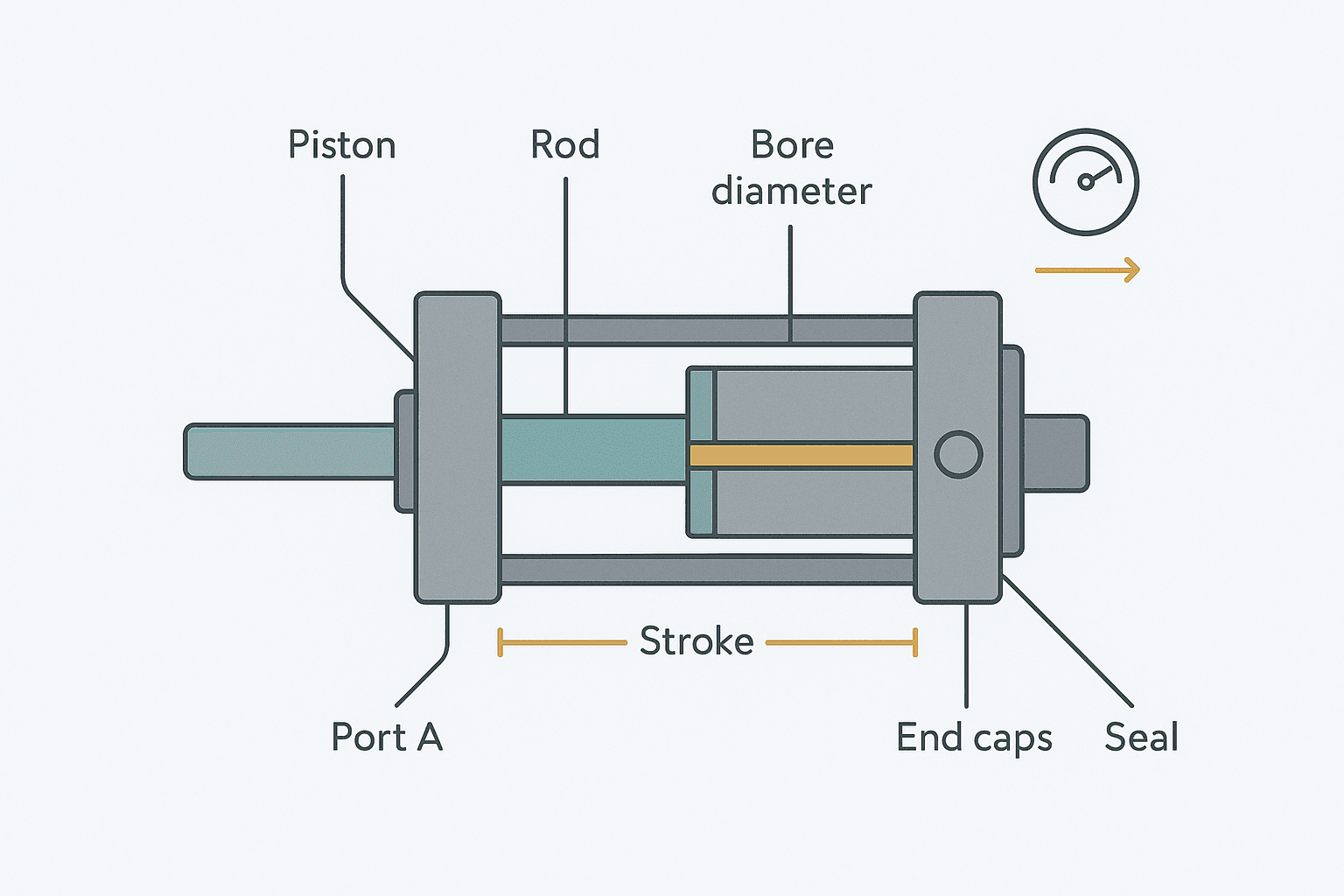
A pneumatic cylinder converts compressed air pressure into linear mechanical force. That is the whole job. Compressed air enters one port, pushes on the piston face, and the rod either extends or retracts. A double-acting cylinder uses air on both sides of the piston so you get powered movement in both directions. A single-acting cylinder uses air in one direction only and relies on a spring or gravity for the return.
The three numbers that define any cylinder are bore diameter, stroke length, and operating pressure. Every other spec, including rod diameter, cushioning, and mounting style, flows from those three. Get them right and the rest is straightforward.
Calculating Bore Diameter from Required Force
Force output is simply pressure multiplied by the effective piston area, then derated for friction and efficiency. The formula for the extend stroke (full bore area) is:
F = P x A x η

Where:
  F = output force (N)
  P = supply pressure (Pa)  [1 bar = 100,000 Pa]
  A = piston area (m²)  = π/4 x D²
  η = efficiency factor (typically 0.85 to 0.90 for standard cylinders)

Rearranged to find minimum bore diameter:
  D = sqrt( (4 x F) / (π x P x η) )

Example:
  Required force = 2000 N
  Supply pressure = 6 bar = 600,000 Pa
  η = 0.85

  A = 2000 / (600,000 x 0.85) = 0.003922 m² -- wait, that's wrong
  A = 2000 / (600,000 x 0.85) = 0.000003922 m²  (3922 mm²)
  D = sqrt(4 x 0.000003922 / π) = 0.0707 m = 70.7 mm

Select next standard bore up: 80 mm bore cylinderThe retract stroke delivers less force because the rod occupies some of the piston area. If your application needs the same force on the return stroke, size for that condition instead. A 32 mm rod in an 80 mm bore cylinder, for example, reduces the annular area to about 3820 mm² versus the full 5027 mm² on the extend side, which is roughly a 24% force reduction.
Choosing Stroke Length Without Over-Specifying
Stroke is the total travel from fully retracted to fully extended. Add 5 to 10 mm of clearance at each end beyond your actual required movement, then pick the nearest standard stroke. Many manufacturers offer adjustable stops or position sensors anyway, so buying the exact theoretical stroke is rarely necessary.
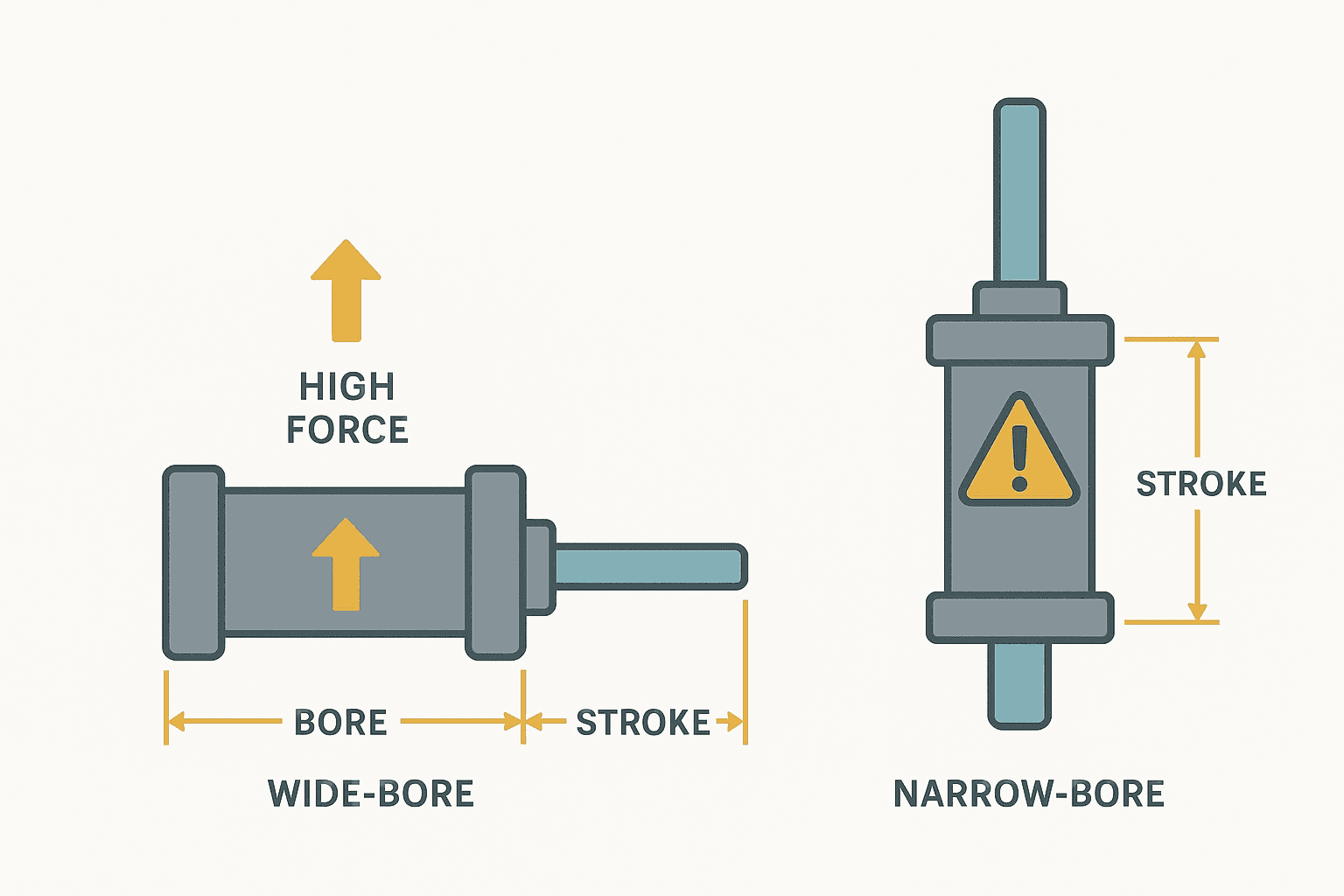
Long strokes create a rod buckling risk. The rod is a column in compression on the extend stroke, and long thin rods can buckle under modest loads. The safe limit depends on the rod diameter, the stroke, and whether the rod end is guided. Most cylinder manufacturers publish load charts for this, and the general rule is that if your stroke exceeds about 10 times the rod diameter, check the buckling chart. Festo, SMC, and Parker all publish free sizing software that handles this automatically.
Operating Pressure: What the Plant Actually Delivers
Do not design to the compressor nameplate pressure. By the time air travels through the distribution system, filter-regulator-lubricator (FRL) units, solenoid valves, and tubing runs, you can easily lose 1 to 2 bar. I have seen plants nominally at 7 bar where the cylinder port sees 4.5 bar at peak demand. Measure at the cylinder port under load, not at the compressor outlet.
A safe design pressure for sizing is usually 5 to 5.5 bar even in a 7 bar plant, unless you have measured otherwise. This gives you a buffer without forcing you into the next bore size up on most applications.
Single-Acting vs Double-Acting: Which One to Use
| Criterion | Single-Acting (spring return) | Double-Acting |
|---|---|---|
| Force on return stroke | Spring only, typically 30-50% of extend force | Full air pressure, nearly equal to extend |
| Fail-safe position | Returns to spring-home on air loss | Stays wherever it stopped on air loss |
| Air consumption | Lower (one port only) | Higher (both ports used) |
| Stroke limit | Usually 100 mm max due to spring length | Up to several metres |
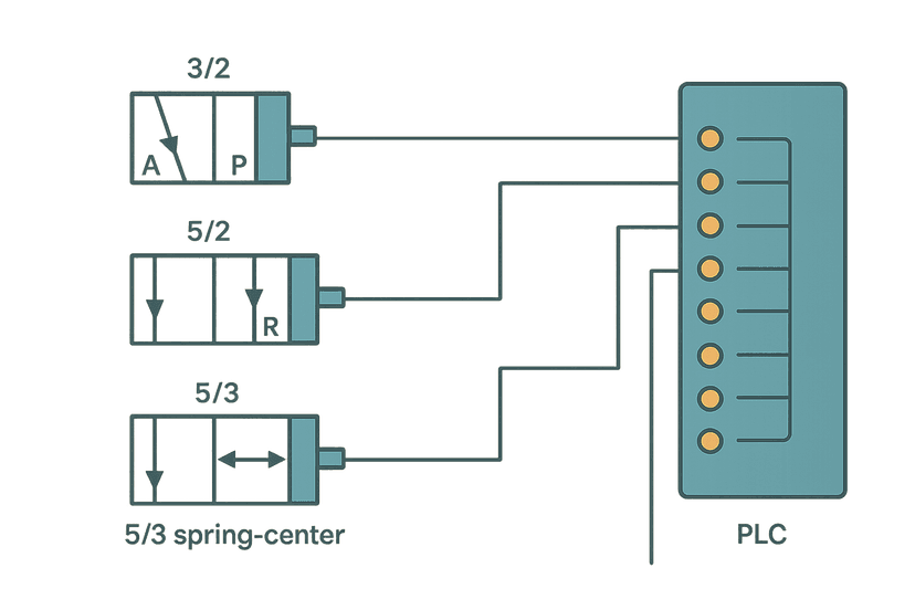
| Complexity | One port, simpler valving | Two ports, 5/2 or 5/3 valve needed |
| Typical use | Clamping, pushing, spring-return grippers | Positioning, pressing, long travel |
For safety-critical clamping where you want the clamp to close on air loss, a single-acting spring-extend cylinder is the right answer. For a pick-and-place slide that needs controlled speed in both directions, double-acting is almost always better.
Cylinder Speed and Flow Rate
Speed is controlled by the flow rate into and out of the cylinder, which is why you fit flow control valves (needle valves with a check) at the cylinder ports. Meter-out control, where you restrict the exhaust air, gives much smoother and more controllable motion than meter-in. This is the standard approach for most applications. Meter-in is only appropriate when the load is always opposing the motion, which is rare.
To estimate cycle time, calculate the volume swept by the piston (bore area times stroke), then divide by your available flow rate. A 63 mm bore cylinder with a 200 mm stroke sweeps about 624 cm³ per stroke. At a flow rate of 200 L/min through a 5/2 solenoid valve, the theoretical extend time is under 0.2 seconds. In practice you will be throttling the flow control valve to slow it down for controlled contact with the load.
Mounting and Rod End Selection
Misalignment between the cylinder axis and the load direction is the biggest cause of premature seal and bearing wear. If your load cannot be perfectly aligned, use a clevis or flange mount on the body and a rod eye or clevis on the rod end. This gives you some angular float. Rigid front flange mounts with a rigid rod coupling are fine only when alignment is guaranteed, which in practice means it is machined and fixed, not adjusted by hand during installation.
Cushioning and End-of-Stroke Shock
At the end of stroke, a fast-moving piston carries kinetic energy that has to go somewhere. Built-in air cushions (adjustable needle valves that trap a pocket of air ahead of the piston) absorb this energy without external shock absorbers. They are standard on most ISO 15552 profile cylinders above 40 mm bore. Adjust them so the piston decelerates smoothly in the last 10 to 20 mm of travel with no audible clunk. If the cylinder is still banging after cushion adjustment, the speed is too high for the cushion capacity and you need an external hydraulic shock absorber.
A Quick Sizing Reference
| Bore (mm) | Piston Area (cm²) | Force at 5 bar x 0.85 (N) | Force at 6 bar x 0.85 (N) |
|---|---|---|---|
| 25 | 4.9 | 208 | 250 |
| 32 | 8.0 | 341 | 409 |
| 40 | 12.6 | 534 | 641 |
| 50 | 19.6 | 833 | 1000 |
| 63 | 31.2 | 1325 | 1590 |
| 80 | 50.3 | 2135 | 2563 |
| 100 | 78.5 | 3336 | 4003 |
| 125 | 122.7 | 5215 | 6258 |
Use this table for a first-pass check. Then verify rod buckling for strokes over 300 mm and check the retract force if the return stroke is load-bearing.
The Practical Checklist Before You Order
- Confirm the actual load force including any friction, gravity component, and process resistance.
- Measure or estimate real supply pressure at the cylinder port under demand, not at the compressor.
- Calculate minimum bore using F = P x A x η, then round up to the next ISO standard size.
- Check rod buckling if stroke is more than 10 times the rod diameter.
- Confirm double-acting is needed, or if single-acting spring return meets the fail-safe requirement.
- Choose mounting style based on whether alignment can be guaranteed.
- Specify built-in cushioning for any bore above 40 mm or speed above 0.3 m/s.
- Add flow control valves at the cylinder ports, meter-out configuration.
- Verify the solenoid valve Cv rating supports the required flow at your pressure drop.
Frequently asked questions
How do I calculate the force output of a pneumatic cylinder?
What is the difference between single-acting and double-acting pneumatic cylinders?
Why does my pneumatic cylinder stall under load even at full pressure?
How do I stop a pneumatic cylinder from banging at the end of stroke?
What causes premature seal failure in pneumatic cylinders?
When should I check for rod buckling in a pneumatic cylinder?
Learn this by building it
There is a PLC in this site. It runs a real scan engine, checks your logic against the same tests a working machine would fail, and needs no download and no account.
Open the exercisesFree, no signup, runs in your browser. See all 16 exercises.
Was this helpful?