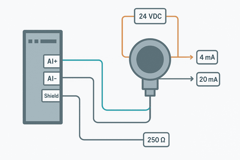
4-20 mA Scaling Formula: The PLC Engineer's Guide
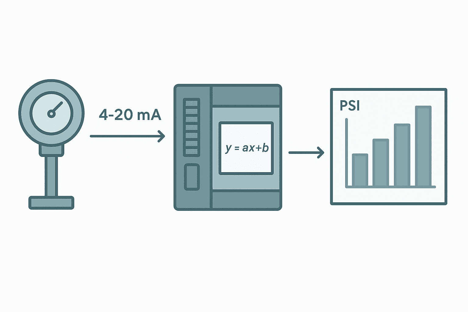
Every 4-20 mA transmitter sends you a current that represents a physical value, say 0 to 200 PSI or -40 to 150 °C. Your PLC's analog input module turns that current into a raw integer count. The gap between that raw count and the number you actually want to display, log or act on is the scaling problem. Get it wrong and your HMI shows 47 PSI when the actual pressure is 0, or your high-pressure interlock trips at the wrong setpoint. Get it right and it is just a formula.
The 4-20 mA Scaling Formula
The relationship between current and the measured value is linear, so the scaling is a straight-line interpolation. The general form is:
That is it. Everything else is just knowing what Raw_min and Raw_max are for your specific module, and deciding what to do with out-of-range counts.
Raw Count Ranges by Platform
This is where most confusion lives. Different vendors use different ADC resolutions and different count conventions. The formula is the same; the numbers you plug in are not.
| Platform / Module | Count at 4 mA (Raw_min) | Count at 20 mA (Raw_max) | Notes |
|---|---|---|---|
| Siemens S7-1200 AI (SM 1231) | 5530 | 27648 | 0-27648 = 0-20 mA range; 4 mA sits at 5530 |
| Siemens S7-300/400 AI | 6912 | 27648 | Same 27648 top; 4 mA = 6912 |
| Rockwell 1756-IF16 (0-21 mA mode) | 3277 | 16383 | 12-bit effective; some configs use 0-32767 |
| Rockwell 1769-IF4 (4-20 mA) | 6242 | 31208 | Scaled counts; check module config page |
| CODESYS generic 12-bit AI | 819 | 4095 | 0-4095 for 0-20 mA; 4 mA = 819 |
| Omron NX-AD (16-bit, 4-20 mA) | 6554 | 32767 | Check IO-Data tab in Sysmac Studio |
| Mitsubishi Q64AD (4-20 mA mode) | 0 | 4000 | Factory default; software offset applied |
Worked Example: 0-200 PSI Pressure Transmitter on a CODESYS 12-bit Input
Say you have a 0-200 PSI pressure transmitter wired to a generic 12-bit analog input module configured for 4-20 mA. The module outputs 0-4095 counts for 0-20 mA.
- Raw_min = 819 (4 mA on a 12-bit 0-20 mA range: 4/20 × 4095 = 819)
- Raw_max = 4095 (20 mA)
- EU_min = 0 PSI
- EU_max = 200 PSI
- Span = Raw_max - Raw_min = 4095 - 819 = 3276 counts
If the module reads 2457 counts:
EU = 0 + 200 × (2457 - 819) / 3276 = 200 × 1638 / 3276 = 200 × 0.5 = 100 PSI
At 2457 counts the transmitter is sitting at half-scale, which is exactly 12 mA. Makes sense.
Scaling in Structured Text (CODESYS / IEC 61131-3)
Here is a clean, reusable function block that does the job. I use REAL math throughout to avoid integer truncation errors, and I clamp the output so a broken cable (counts below 819) does not send a wild negative number to your control logic.
FUNCTION_BLOCK FB_ScaleAnalog
VAR_INPUT
    rawValue   : INT;     (* Raw ADC count from module *)
    rawMin     : INT;     (* Count at 4 mA, e.g. 819 for 12-bit 0-20 mA *)
    rawMax     : INT;     (* Count at 20 mA, e.g. 4095 *)
    euMin      : REAL;    (* Engineering unit at 4 mA, e.g. 0.0 *)
    euMax      : REAL;    (* Engineering unit at 20 mA, e.g. 200.0 *)
    clampOutput: BOOL;    (* TRUE = clamp result to euMin..euMax *)
END_VAR
VAR_OUTPUT
    euValue    : REAL;    (* Scaled engineering unit result *)
    underRange : BOOL;    (* Raw below rawMin = wire break / short *)
    overRange  : BOOL;   (* Raw above rawMax = overload or fault *)
END_VAR
VAR
    span       : REAL;
    ratio      : REAL;
END_VAR

span := REAL#1.0 * (rawMax - rawMin);

IF span = 0.0 THEN
    (* Protect against divide-by-zero if misconfigured *)
    euValue   := euMin;
    underRange := FALSE;
    overRange  := FALSE;
    RETURN;
END_IF

ratio    := (INT_TO_REAL(rawValue) - INT_TO_REAL(rawMin)) / span;
euValue  := euMin + ratio * (euMax - euMin);

underRange := rawValue < rawMin;
overRange  := rawValue > rawMax;

IF clampOutput THEN
    IF euValue < euMin THEN euValue := euMin; END_IF
    IF euValue > euMax THEN euValue := euMax; END_IF
END_IF
Call it from your main program like this:
VAR
    fbPressure : FB_ScaleAnalog;
    Pressure_PSI : REAL;
    PressureWireFault : BOOL;
END_VAR

(* Called every scan *)
fbPressure(
    rawValue    := AI_Channel1,    (* word from analog input module *)
    rawMin      := 819,
    rawMax      := 4095,
    euMin       := 0.0,
    euMax       := 200.0,
    clampOutput := TRUE
);

Pressure_PSI   := fbPressure.euValue;
PressureWireFault := fbPressure.underRange;underRange flag is your wire-break detector. If the current loop is open, the raw count will drop to zero, well below 819. Latch an alarm on that flag rather than acting on the nonsense EU value.The 3 to 15 PSI Pneumatic Case
One search that comes up a lot is '4-20 mA scaling 3 to 15 PSI'. This is the classic I/P transducer range: 4 mA drives a pneumatic output of 3 PSI, 20 mA drives 15 PSI. Same formula, just different EU limits:
- EU_min = 3.0 (PSI output at 4 mA)
- EU_max = 15.0 (PSI output at 20 mA)
- Use the same Raw_min and Raw_max for your module as before
On a 12-bit module, mid-scale 2457 counts gives: EU = 3 + (15-3) × 0.5 = 3 + 6 = 9 PSI. That is the control point for most spring-diaphragm control valves at 50% lift. Everything lines up.
Siemens S7 Quick Version: NORM_X and SCALE_X
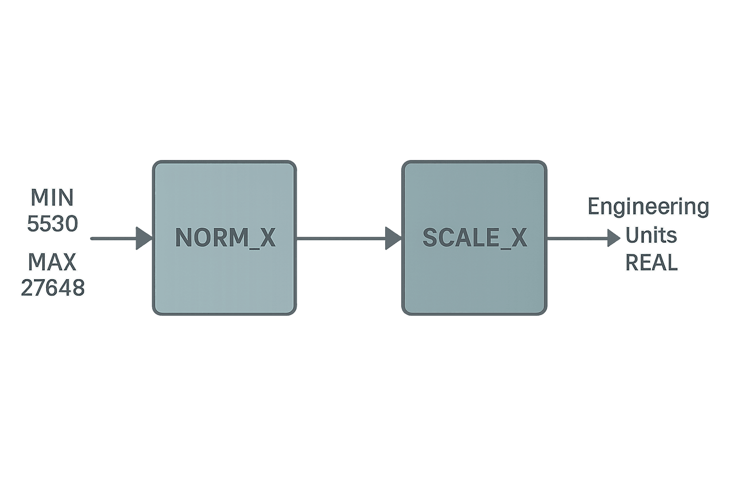
TIA Portal has built-in instructions for this. NORM_X normalises a raw count to a 0.0-1.0 REAL, and SCALE_X maps that to any EU range. Two instructions chained together. The parameters MIN and MAX in NORM_X are where you enter your raw count limits. For an S7-1200 in 4-20 mA mode, set MIN = 5530 and MAX = 27648.
The underlying math is identical to the formula above. NORM_X calculates the ratio, SCALE_X applies it to your EU span. If you understand the formula you can debug NORM_X/SCALE_X problems instantly, which matters when a technician sets the wrong MIN value on site and the reading drifts by 10%.
Common Scaling Mistakes and How to Avoid Them
- Using 0 for Raw_min instead of the 4 mA count. If you scale from 0-4095 instead of 819-4095, your zero reading will be wrong by about 20% of span. On a 0-200 PSI transmitter that is a 40 PSI error at zero current.
- Integer math truncation. Doing (Raw - Raw_min) / (Raw_max - Raw_min) in integer arithmetic in some PLCs truncates to 0 for any input below full scale. Cast to REAL first.
- Ignoring the underRange flag. A broken cable gives you a stable, believable low reading if you clamp without alarming. Add the wire-break alarm.
- Mixing up module config and formula. Some modules let you configure them to output pre-scaled REAL values directly (e.g. 0.0 to 100.0%). If you then apply your own formula on top, you double-scale. Check the module output data type in your I/O tree.
- Not accounting for transmitter live zero vs dead zero. A HART transmitter with 4 mA live zero means 4 mA = valid zero reading. A 0-20 mA transmitter with 0 mA = zero has no wire-break detection. Know which you have.
Use the Analog Scaling Calculator
If you want to verify your numbers quickly, the analog scaling calculator on this site lets you plug in raw counts and EU limits and see the result instantly. Useful for commissioning checks or for explaining the math to a technician on site. You can also use it to reverse-engineer a raw count from a known EU value, which is handy when you are bench-testing a transmitter with a loop calibrator.
Wiring Basics Affect Scaling Accuracy
Scaling math is only as good as the signal feeding it. A voltage drop across a long cable run or a corroded terminal can shift the current seen by the module by 0.2-0.5 mA. On a 16 mA span that is 1-3% error before you even open the PLC. If your scaled value is consistently high or low and the transmitter checks out at the head, measure the actual current at the module terminals with a calibrated clamp meter. For more on getting the wiring right, see PLC Analog Input Wiring: 4-20 mA Step by Step.
Scaling Output Signals: PLC to I/P Transducer
The formula works in reverse for analog outputs too. You have an EU value in the PLC (say, a valve position setpoint in percent) and you need to write a raw count to an analog output module that drives a 4-20 mA output.
Clamp the output too. Writing a raw count above 4095 on a 12-bit module does nothing useful, and writing a negative number can cause module faults on some hardware.
Frequently asked questions
What is the 4-20 mA scaling formula for a PLC?
What raw count does 4 mA equal on a Siemens S7-1200?
How do I detect a broken 4-20 mA wire in a PLC?
How do I scale 4-20 mA to 3-15 PSI for a pneumatic I/P transducer?
Why is my scaled analog value wrong by a fixed offset at zero?
Can I use the same scaling formula for analog outputs?
Learn this by building it
There is a PLC in this site. It runs a real scan engine, checks your logic against the same tests a working machine would fail, and needs no download and no account.
Open the exercisesFree, no signup, runs in your browser. See all 16 exercises.
Was this helpful?