PLC Analog Input Wiring: 4-20 mA Step by Step
Analog input wiring is one of those things that looks simple on paper and then bites you on commissioning day. A pressure transmitter reading 0 % when the tank is half full, a signal that jumps 2 % every time a contactor closes nearby, a module that shows overrange even though the sensor is fine. Most of these faults trace back to wiring decisions made at the panel, not the instrument itself.
This post covers everything you need to wire a 4-20 mA transmitter to a PLC analog input card correctly: the difference between 2-wire, 3-wire and 4-wire devices, how to pick the right terminal on the module, shielding and grounding rules, and how to turn the raw ADC count into engineering units inside the PLC. Examples use the Siemens S7-1200/S7-1500 SM 1231 analog input module, but the principles apply to any platform.
Why 4-20 mA, Not 0-10 V?
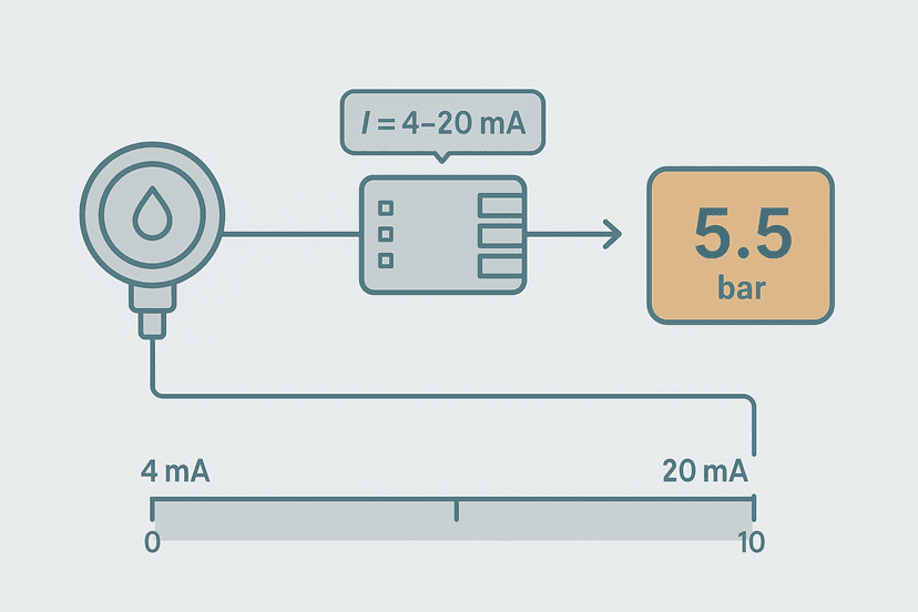
Current loops are the default choice in industrial instrumentation for three reasons. First, current does not drop across long cable runs the way voltage does. A 100-metre run of 0.5 mm² cable has roughly 7 ohms of resistance each way. At 20 mA that is a 280 mV drop, which matters to a 0-10 V input but is completely invisible to a current receiver. Second, a broken wire goes to 0 mA, which is below the live-zero of 4 mA, so your PLC can detect a wire-break condition without extra hardware. Third, the 4 mA live-zero also powers 2-wire transmitters directly from the loop, so you need only two conductors from the field.
2-Wire, 3-Wire and 4-Wire Transmitters: What Actually Differs
The number of wires describes how the transmitter is powered and how the signal returns, not the sensor type.
| Type | Power source | Signal return | Typical use |
|---|---|---|---|
| 2-wire (loop-powered) | Loop current from external 24 VDC supply through the AI module | Same two conductors as power | Pressure, level, temperature transmitters in hazardous or remote areas |
| 3-wire (source-powered) | Separate 24 VDC supply to transmitter; 0 V common shared with signal return | Dedicated signal- wire back to module AI- | Flow transmitters, some proximity-based sensors |
| 4-wire (self-powered) | Separate 24 VDC supply to transmitter, fully isolated from signal circuit | Dedicated signal+ and signal- back to module | Analyzers, high-accuracy instruments, devices with display |
The most common mistake I see is wiring a 3-wire transmitter as if it were a 4-wire device and floating the signal return. The module sees no current reference and the reading oscillates. Always check the transmitter datasheet for the pinout before you touch the terminal block.
Step-by-Step Wiring: 2-Wire Transmitter to S7-1200 SM 1231
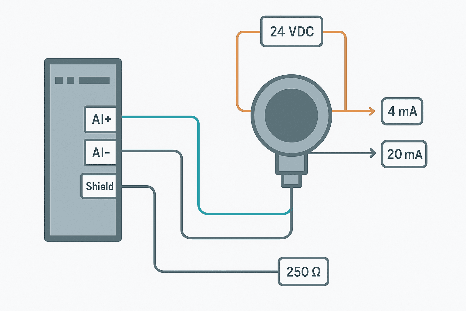
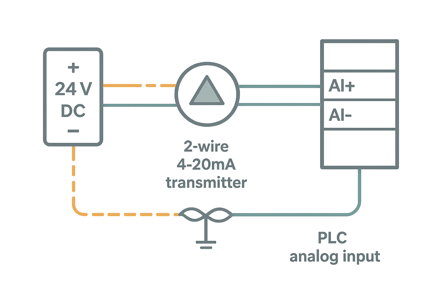
The SM 1231 uses a sourcing input architecture. For a 2-wire loop-powered transmitter the wiring is:
- 24 VDC (+) from your panel supply to the transmitter + terminal (red wire).
- Transmitter output terminal (usually marked + or SIG) to AI+ on the module terminal block.
- AI- on the module back to 24 VDC common (0 V). This completes the loop.
- Cable shield connected to the panel earth rail at the panel end only. Leave the field end floating.
Wiring a 4-Wire Transmitter
A 4-wire device has its own internal power supply, so the signal circuit is separate. Wire it like this:
- 24 VDC (+) to transmitter PWR+ terminal.
- 24 VDC (0 V) to transmitter PWR- terminal.
- Transmitter SIG+ to AI+ on the module.
- Transmitter SIG- to AI- on the module.
- Cable shield to panel earth at panel end only.
Because the power and signal circuits are isolated inside the transmitter, you have no ground loop risk from the power supply side. That isolation is the reason 4-wire devices are preferred for high-accuracy applications: the signal return is clean and independent of any power supply common noise.
Cable Selection and Routing
Use shielded twisted-pair (STP) cable rated for the environment. In most process plants that means a 2-core or 2-pair instrument cable with an overall foil shield and drain wire, something like Belden 8762 or its equivalent. Minimum conductor size is typically 0.5 mm² (AWG 20) for mechanical durability, though electrically even 0.2 mm² would pass 20 mA without trouble on runs under 200 m.
- Route analog cables in a separate trunking from 230/400 VAC power cables. If they must cross, cross at 90 degrees.
- Keep at least 150 mm separation from variable-frequency drive output cables. VFD cables are the worst offenders for induced noise.
- Do not run analog cables alongside contactor coil wiring or solenoid valve cables.
- Terminate the drain wire at the panel earth bar with a short pigtail. Trim the field end and insulate it with heat-shrink so it cannot accidentally contact metalwork.
Scaling Raw Counts to Engineering Units in TIA Portal
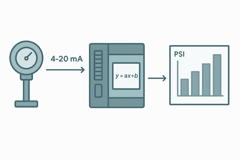
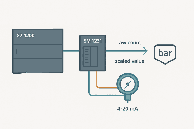
The SM 1231 in current mode delivers a 16-bit signed integer (Word) to the process image. At 4 mA the raw value is 5530 and at 20 mA it is 27648. Those numbers come from the Siemens scaling definition: 0 mA = 0, 20 mA = 27648, so 4 mA = 27648 × (4/20) = 5530. You scale this to engineering units (say 0 to 100 % level) with the NORM_X and SCALE_X instructions in a function block.
// Scale raw analog count to engineering units (Siemens TIA Portal SCL)
// Input:  AI_RawCount  (INT)  - raw value from SM 1231, 5530..27648 for 4..20 mA
// Output: Level_Pct    (REAL) - engineering value in percent, 0.0..100.0

FUNCTION_BLOCK FB_ScaleAnalog
VAR_INPUT
    AI_RawCount : INT;
    RawMin      : INT := 5530;   // 4 mA
    RawMax      : INT := 27648;  // 20 mA
    EUmin       : REAL := 0.0;   // 0 %
    EUmax       : REAL := 100.0; // 100 %
END_VAR
VAR_OUTPUT
    EU_Value    : REAL;
    WireBreak   : BOOL;          // TRUE if signal below 4 mA live-zero
END_VAR
VAR
    Normalized  : REAL;
END_VAR

// Detect wire-break: raw count significantly below 4 mA level
WireBreak := (AI_RawCount < 4000);

// Clamp raw count to valid range before scaling
Normalized := NORM_X(MIN := INT_TO_REAL(RawMin),
                     VALUE := INT_TO_REAL(AI_RawCount),
                     MAX := INT_TO_REAL(RawMax));

EU_Value := SCALE_X(MIN := EUmin,
                    VALUE := Normalized,
                    MAX := EUmax);

END_FUNCTION_BLOCK
The WireBreak output uses the 4 mA live-zero as a fault detector. If the transmitter cable is cut or the transmitter loses power, the loop current falls to 0 mA and the raw count drops to around 0. A threshold of 4000 (roughly 2.9 mA) gives you a clean wire-break flag without false alarms from a transmitter sitting at its minimum calibrated value. You can drive that flag to an alarm tag on your HMI or handle it in safety logic.
Common Faults and How to Diagnose Them
| Symptom | Most likely cause | Quick check |
|---|---|---|
| Raw count stuck at 0 or near 0 | Wire break or transmitter not powered | Measure loop current with clamp meter at panel terminal |
| Raw count at maximum (32767 or similar) | Signal wire polarity reversed, or AI+ shorted to 24 V | Check wiring at both ends; reverse the two signal cores |
| Signal noisy, jumps 2-5 % | Shield grounded at both ends, or cable runs near VFD | Lift shield at field end; re-route cable away from drives |
| Signal reads low by a fixed offset | Wrong RawMin in scaling block, or transmitter zero not trimmed | Inject 4 mA with a loop calibrator and check raw count against 5530 |
| Channel error LED on module | Module configured for voltage but transmitter wired for current, or open-circuit detected | Verify module channel parameter in hardware config (TIA Portal device view) |
A Few Things Worth Knowing Before You Commission
The SM 1231 needs the channel mode set to 'Current' (not 'Voltage') in TIA Portal hardware configuration, otherwise you get nonsense readings even with perfect wiring. It sounds obvious, but I have lost an hour to exactly that. Go to Device Configuration, double-click the analog module, open the channel properties, and confirm the input type is set to '4 to 20 mA' not '0 to 10 V'.
Also, the S7-1200 SM 1231 does not have built-in isolation between channels. If you have two transmitters powered from different 24 V supplies with different 0 V references, you can get a common-mode voltage between the two AI- terminals. That will corrupt both channels. Either use a single common 24 V supply for all loop-powered devices on one module, or use transmitters with isolated outputs, or fit signal isolators (loop-powered types like the Phoenix Contact MCR-SL-RPSSI-I-I work well and cost under 30 EUR each).
If you are working on a panel design and need to size the fusing for the 24 VDC instrument supply circuit, the post on fuse and breaker selection for control panels has the calculation method for DC circuits with multiple loads.
Quick Reference: Terminal Connections Summary
| Transmitter type | Transmitter terminal | Connects to |
|---|---|---|
| 2-wire | TX+ (or L+) | 24 VDC (+) from panel supply |
| 2-wire | TX- (or L-) | AI+ on module |
| 2-wire | AI- on module | 24 VDC (0 V) common |
| 3-wire | PWR+ | 24 VDC (+) |
| 3-wire | PWR- / COM | 24 VDC (0 V) AND AI- on module (shared common) |
| 3-wire | SIG+ | AI+ on module |
| 4-wire | PWR+ | 24 VDC (+) |
| 4-wire | PWR- | 24 VDC (0 V) |
| 4-wire | SIG+ | AI+ on module |
| 4-wire | SIG- | AI- on module |
Frequently asked questions
What is the difference between a 2-wire and 4-wire transmitter for a PLC analog input?
Why does my PLC analog input read 0 even though the transmitter is powered?
Should I ground the cable shield at both ends for a 4-20 mA analog signal?
What raw count values should I expect from a Siemens S7-1200 SM 1231 at 4 mA and 20 mA?
How can my PLC detect a broken wire on a 4-20 mA analog input?
Can I run a 4-20 mA signal cable next to a VFD output cable?
Now build it
You have just read about MCR. Reading a rung and making one behave are different skills, and the second one is the job.
State Coil / Fault Coil
Intermediateabout 15 minA fault lamp that latches ON when any alarm condition occurs, even briefly, and only clears on Reset. And if the condition is still present when Reset is released, the fault comes right back.
Build this rungFree, no signup, runs in your browser. See all 16 exercises.
Was this helpful?