Pneumatic Solenoid Valves: Types, Wiring and PLC Control
The solenoid valve is where PLC logic becomes physical movement. Get the valve type wrong and your cylinder either won't retract on power loss, will float mid-stroke, or will need two output cards instead of one. This post cuts through the naming convention confusion, explains which configuration to use for each application, and shows you exactly how to wire and program them.
Pneumatic Solenoid Valve Naming: What the Numbers Actually Mean
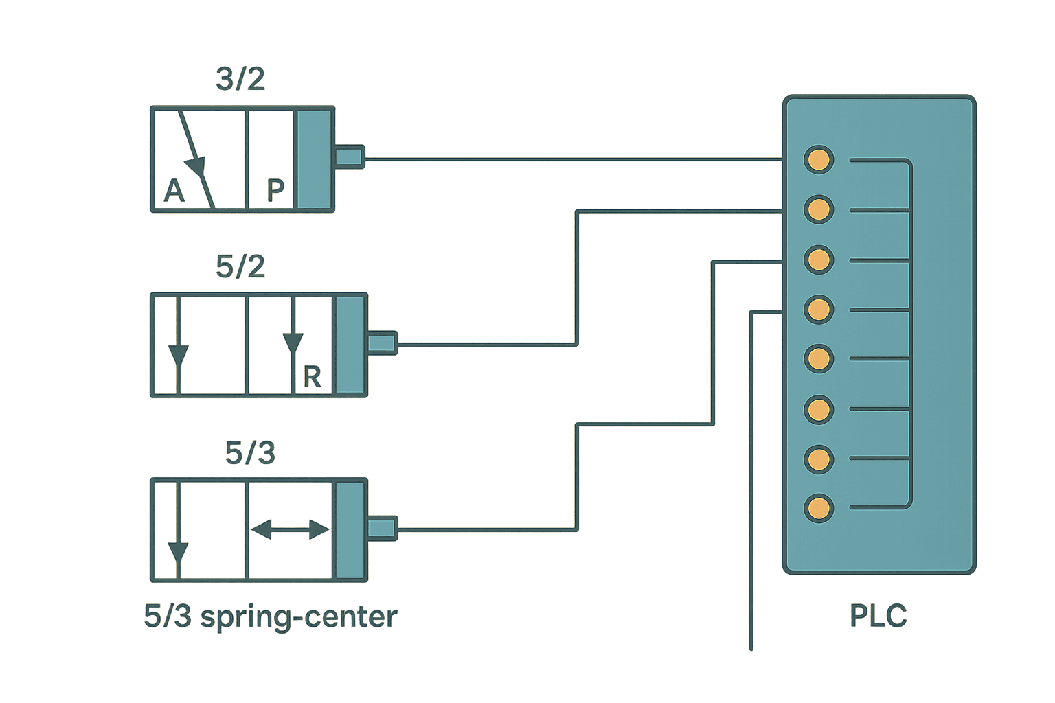
Every directional control valve gets a two-number designation: ports / positions. A 5/2 valve has 5 ports and 2 positions. A 5/3 has 5 ports and 3 positions. That's the whole system.
Ports are numbered (or lettered) according to ISO 1219. The standard port labels are: 1 (P) = pressure supply, 2 (A) = cylinder port A, 4 (B) = cylinder port B, 3 (R) = exhaust from port A side, 5 (S) = exhaust from port B side. On a 3/2 valve you only have ports 1, 2 and 3 because there's only one working port.
| Designation | Ports | Positions | Typical actuator | Fail-safe |
|---|---|---|---|---|
| 2/2 | 2 | 2 | Clamp, blow-off | Closed or open |
| 3/2 NC | 3 | 2 | Single-acting cylinder | Retract on de-energise |
| 3/2 NO | 3 | 2 | Single-acting cylinder | Extend on de-energise |
| 5/2 monostable | 5 | 2 | Double-acting cylinder | Returns to spring side |
| 5/2 bistable | 5 | 2 | Double-acting cylinder | Holds last position |
| 5/3 spring-center | 5 | 3 | Double-acting, mid-stop needed | Centers (blocked or exhausted) |
Monostable vs Bistable: The Choice That Matters Most
This is the decision that bites engineers most often. A monostable (single-solenoid) valve has one coil and a return spring. Energise the coil and the spool shifts. Cut power and the spring pushes it back. One PLC output controls it. Simple.
A bistable (double-solenoid) valve has a coil on each end. You pulse one coil to shift the spool, pulse the other to shift it back. The spool holds position with no power applied, which is genuinely useful on long-stroke clamps where you don't want to hold a solenoid energised for 30 seconds. The trade-off: you need two PLC outputs and you must add interlock logic to prevent both coils being energised simultaneously. That's a very real failure mode if someone writes the logic carelessly.
5/3 Valves and the Three Center Conditions
A 5/3 valve adds a center (neutral) position between the two working positions. When both solenoids are de-energised, the spool springs to center. What happens in center depends on the spool type:
- Closed center (all ports blocked): cylinder locks in place. Good for clamping a workpiece mid-stroke. Watch out: if there's a load pushing on the rod, pressure will build until a seal leaks.
- Pressure center (both cylinder ports connected to supply): cushions the cylinder against shock. Used on vertical axes where you want both sides pressurised to hold position against gravity.
- Exhaust center (both cylinder ports open to exhaust): cylinder rod floats free. Used where you need to manually push the rod without fighting back-pressure, common on tooling change fixtures.
In practice, closed-center is the most common choice for machine tools. Exhaust-center shows up in assembly fixtures. Pressure-center is relatively rare and you'll see it called out explicitly in the pneumatic schematic notes.
Wiring a Solenoid Valve to a PLC Output
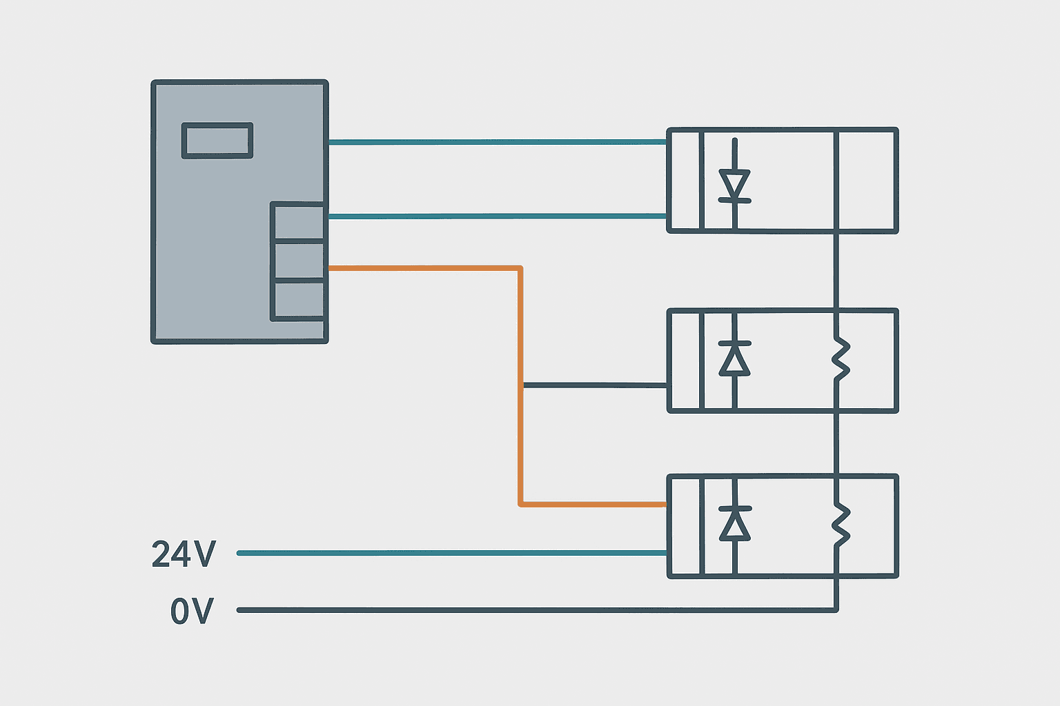
Most industrial solenoid valve coils run on 24 VDC and draw 0.5 to 2.5 W. That's well within the capacity of a standard transistor (sourcing) PLC output card, which is typically rated 0.5 A per point. Relay output cards can switch them too but the contact life on small relay outputs is shorter than people expect when you're cycling a clamp valve 60 times per minute.
Coil voltages vary: 24 VDC is by far the most common, but you'll encounter 110 VAC and 230 VAC coils on older machines or where the system uses AC I/O. Always check the coil label, not just the manifold nameplate, because manifolds can be mixed. A 24 VDC coil driven from 110 VAC will fail immediately. A 110 VAC coil driven from 24 VDC simply won't shift.
Suppression Diodes: Don't Skip Them on DC Coils
When a solenoid coil de-energises, it generates a voltage spike that can be 10 to 100 times the supply voltage, lasting microseconds. On a 24 VDC system that spike can reach 200 to 300 V. A flyback diode across the coil (cathode to positive, anode to negative) clamps this to about 0.7 V above supply and protects the transistor output. Most modern valve coils have a suppression diode or TVS built into the connector. If you're wiring bare coil terminals, add an external 1N4007 or equivalent. This is standard practice and ignoring it is a silent killer of output cards over months of operation.
PLC Logic for a Bistable 5/2 Valve with Interlocks
Here's what actually matters in the program for a bistable valve controlling a double-acting clamp cylinder. The cylinder has two sensors: Clamp_Extended and Clamp_Retracted. The valve has two outputs: Sol_Clamp_Extend (solenoid A) and Sol_Clamp_Retract (solenoid B). The key rule: never command both coils at once, and only command extend when retract is not already commanded, and vice versa.
Bistable 5/2 Valve: Extend/Retract Interlocked Rungs (Studio 5000). Ladder logic (2 rungs): Rung 0: examine if Cycle_Run is on (XIC), then examine if Clamp_Extended is off (XIO), then examine if Sol_Clamp_Retract is off (XIO), then energize output Sol_Clamp_Extend (OTE). Rung 1: examine if Part_Released is on (XIC), then examine if Clamp_Retracted is off (XIO), then examine if Sol_Clamp_Extend is off (XIO), then energize output Sol_Clamp_Retract (OTE). Rung 1: Extend command is only allowed when the cylinder is not already extended and the retract solenoid is not active. Rung 2: Retract command mirrors the same interlock in the opposite direction. Both rungs use XIO contacts on the opposing solenoid tag to prevent simultaneous coil energisation on the bistable valve.
The diagram above evaluates one scan. Run these exact rungs on a real scan cycle to watch the latching and the timers behave.
Run this in the simulatorManifold Wiring and Multi-Station Setups
On any machine with more than three or four cylinders you'll almost certainly be using a valve manifold rather than individual body-ported valves. Common options are Festo CPX, SMC EX series, or Parker Pro with DeviceNet/EtherNet/IP fieldbus nodes. These replace individual wiring runs back to the panel with a single network cable and a small fieldbus node at the manifold. The PLC sees each solenoid as a bit in an output word, and commissioning time drops dramatically.
The gotcha with manifold fieldbus nodes: the output update rate over the fieldbus adds a few milliseconds of latency compared to hardwired outputs. For most pneumatic applications this is invisible, but if you have a valve that must respond within one scan cycle for a safety-critical purpose, hardwire it directly. Don't route safety-critical solenoid commands through a fieldbus manifold node unless the node itself is a safety-rated device and the SIL calculation accounts for it. The post on Pneumatic Cylinder Sizing: Force, Bore and Stroke covers cylinder selection once you know which valve type you're using.
Fail-Safe Design: Which Valve Type for Which Risk
The right valve type is partly a pneumatic choice and partly a safety decision. Think through what happens on power loss or E-stop before you specify the valve.
- Monostable 5/2, spring-return to retract: safest default for most horizontal clamps and grippers. Power off = cylinder retracts = part releases. No extra logic needed for fail-safe retract.
- Monostable 5/2, spring-return to extend: used where the safe state is extended, e.g. a brake-apply cylinder where spring-extend applies the brake and power releases it.
- Bistable 5/2: correct for long-dwell clamping where you don't want continuous solenoid current, or where the cylinder must hold position through a power micro-dip. Requires more careful logic and a defined safe-state procedure.
- 5/3 closed-center: cylinder locks on E-stop. Useful on vertical axes to prevent drop, but you must verify the cylinder seals and valve leakage rate over time because slow drift is possible.
- 5/3 exhaust-center: cylinder floats on E-stop. Acceptable only where the load cannot cause injury when the rod is free, such as a light part guide.
Common Commissioning Problems
- Valve clicks but cylinder doesn't move: check supply pressure (minimum 2 to 3 bar on most valves), then check for a blocked exhaust silencer. Silencers clog with oil mist over time and create back-pressure that stops the spool from shifting fully.
- Cylinder drifts when valve is centered: worn spool seals or excessive supply pressure past the center spool lands. On older valves, a spool kit costs a fraction of replacement. On a new valve, it's a warranty call.
- Solenoid coil gets hot: coil is being held energised at too high a voltage, or the coil is rated for pulse-width-modulated hold current and you're driving it with a constant 24 VDC. Some valves use a peak-and-hold driver built into the coil connector; if yours doesn't have one, verify the coil duty cycle rating.
- Valve shifts but slowly: flow rate is too low for the cylinder bore. You may need a larger valve Cv, a quick-exhaust valve close to the cylinder port, or both. Don't just crank up the supply pressure.
- Output card trips on overcurrent: measure coil resistance first. A shorted coil can read under 5 ohms and pull 4 to 5 A from a 24 VDC supply, which is well above a 0.5 A transistor output rating.
Frequently asked questions
What is the difference between a 5/2 and a 5/3 pneumatic solenoid valve?
How do I wire a 24 VDC solenoid valve to a PLC output?
What does monostable mean on a solenoid valve?
Can I use a relay output to drive a pneumatic solenoid valve?
Why does a bistable solenoid valve need two PLC outputs?
What is the safe state of a 5/3 closed-center pneumatic valve?
Now build it
You have just read about XIO. Reading a rung and making one behave are different skills, and the second one is the job.
Start / Stop Circuit
Beginnerabout 10 minThe first circuit every controls engineer learns: a motor that starts on a button press, keeps running when the button is released, and stops on a stop button, with stop always winning.
Build this rungFree, no signup, runs in your browser. See all 16 exercises.
Was this helpful?