Control Panel Grounding: The Right Way to Do It
Bad grounding is responsible for more mystery faults, corrupted comms, and fried I/O cards than almost any other wiring mistake. And yet most panels get a single green-yellow wire run from the chassis to earth and call it done. That is not grounding. That is wishful thinking.
This post walks through the correct grounding architecture for an industrial PLC panel, from the main PE bus to signal-ground separation and shield termination. Real numbers, real gotchas, and the mistakes I see in the field almost every time I commission a new machine.
Control Panel Grounding: Why It Actually Matters
Grounding serves three distinct functions in a control panel, and confusing them is where the trouble starts. First, it provides personnel safety: a fault on a live conductor bonds the chassis to earth and trips the upstream overcurrent device. Second, it gives high-frequency noise currents a defined, low-impedance return path so they do not ride through your signal cables. Third, it establishes a stable voltage reference for analog inputs, comms buses, and DC common returns.
Those three functions are sometimes served by the same conductor, but not always. Mixing them carelessly creates ground loops, injects switching noise into 4-20 mA loops, and can shift the reference potential of a PROFIBUS or EtherNet/IP network enough to cause intermittent dropouts. I have seen a single misplaced ground wire add 300 mV of 50 Hz ripple onto an analog channel and fool a PID loop into hunting continuously.
The PE Bus: Your Grounding Foundation
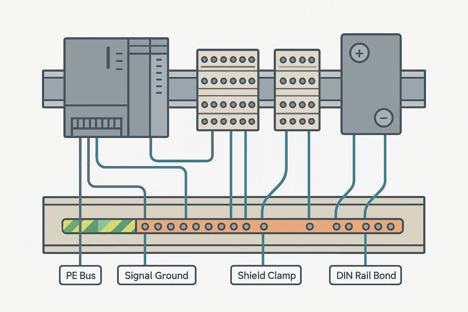
Every panel needs a dedicated protective earth (PE) bus bar, typically a copper bar bolted directly to the back plate with short, fat connections. Short and fat is the key phrase. Ground impedance is dominated by inductance at high frequency, and inductance scales with wire length. A 1-metre run of 6 mm² green-yellow wire has measurable inductance. A 100 mm run of 16 mm² or a direct bolt-down has far less. For a 24 VDC control panel, 6 mm² PE conductors are typically the minimum. For a 230 VAC or 400 VAC panel with motor feeds, size per IEC 60364-5-54.
The DIN rails carry the PLC backplane, power supplies, and I/O modules. Each rail must be bonded to the PE bus with a short jumper, 4 mm² minimum, because the rail itself becomes part of the EMC ground plane. Siemens TIA Portal documentation, Rockwell's wiring guidelines for ControlLogix, and CODESYS platform notes all say the same thing: ground your DIN rail.
24 VDC Common (DC0V) and Its Relationship to PE
This is the area that causes the most confusion. The negative rail of your 24 VDC SELV power supply, often labelled 0V or DC-, is not automatically the same as PE. On a floating SELV supply, 0V and PE are isolated from each other by design. That isolation is intentional and is part of what gives you a safe extra-low-voltage circuit.
The question is whether you bond 0V to PE at one point or keep them fully floating. Most PLC manufacturers recommend a single-point bond of 0V to PE, usually at the power supply output terminal. This controls the common-mode voltage of the 24 VDC rail relative to earth, which matters for EMC and for the protection of input circuits. The critical rule: bond at ONE point only. Multiple bonds create a loop, and that loop is an antenna for magnetically coupled noise from VFD switching, transformer hum, and cable capacitance.
Signal Ground Separation and Analog Wiring
Analog signals, thermocouple inputs, and serial comms all deserve their own ground reference, kept clean and away from the high-current switching paths. In practice this means:
- Run analog cable returns back to a dedicated analog common terminal, not to the general 24 VDC 0V bus.
- Keep analog wiring physically separated from 230 VAC and VFD output cables. A minimum of 100 mm separation or a grounded metal separator is the usual rule of thumb for runs longer than 300 mm.
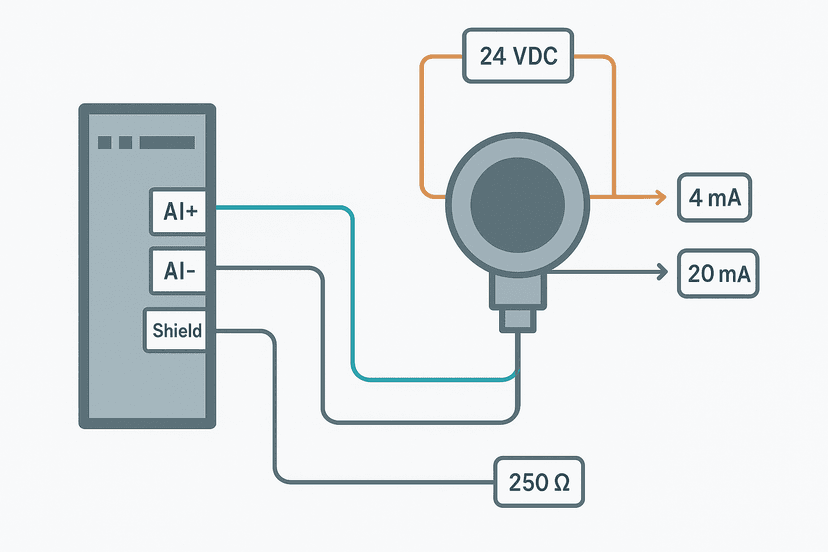
- Use twisted-pair, shielded cable for all 4-20 mA and RTD wiring. Belden 8761 (single-pair) and 8771 (two-pair) are workhorses in North American installations. In Europe, LiYCY or LIYCY-P types are common.
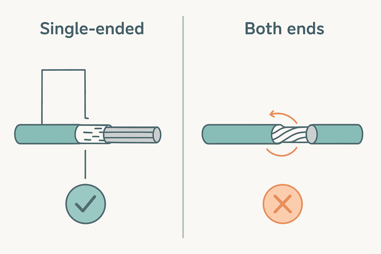
- Terminate shields at the panel end only (single-ended shield termination) to prevent shield currents from flowing and injecting noise into the signal.
Shield Termination Hardware
Do not strip back shielding and twist the drain wire into a 200 mm pigtail before connecting it to the PE bus. That pigtail is an inductor. At the switching frequencies of modern VFDs (4 to 16 kHz carrier), a 200 mm pigtail has enough impedance to be nearly useless as a shield termination. Use a proper EMC cable clamp or shield clamp terminal. Phoenix Contact, Weidmuller, and Rittal all make DIN-mountable clamp blocks that grip the cable jacket and make a 360-degree contact with the braid. That is a real shield termination. A pigtail is not.
Grounding the PLC Rack and I/O Modules
Most modern PLC platforms are designed to use the DIN rail as a functional ground plane. Rockwell ControlLogix and CompactLogix chassis bolt directly to a grounded rail and rely on that contact for high-frequency EMC bonding. Siemens S7-1200 and S7-1500 modules clip to the rail and also have a dedicated functional ground terminal on the power module. Omron NX-series modules use the rail plus a separate FG terminal on the CPU.
Read your platform's installation manual for the specific requirement. The Rockwell publication 1756-IN572 (ControlLogix chassis installation) and the Siemens S7-1500 hardware installation manual both contain grounding diagrams that are worth printing and keeping in the panel folder. They are not suggestions; ignoring them voids EMC compliance.
| Platform | DIN Rail Bond Required? | Separate FG Terminal? | 0V to PE Bond Point |
|---|---|---|---|
| Rockwell ControlLogix | Yes, via chassis mount | No (rail is FG) | At 24V power supply output |
| Siemens S7-1500 | Yes, star washer | Yes, on PM/PS module | At system power supply |
| Omron NX Series | Yes | Yes, on CPU module | At 24V power supply output |
| Beckhoff EtherCAT I/O | Yes, toothed clamp | Yes, on EK1100 coupler | At 24V power supply output |
| CODESYS (generic) | Platform-dependent | Platform-dependent | At 24V power supply output |
VFD and Servo Drive Grounding: The Biggest EMI Source in the Panel
Variable frequency drives are switched-mode power converters running at kilohertz switching frequencies. The common-mode currents they generate are significant and will find the lowest-impedance path to earth, which, if you have not designed that path intentionally, is often your PLC analog wiring. This is the root cause of a huge proportion of the 'ghost faults' and analog noise complaints I get called out to fix.
The rules for VFD grounding in a panel are:
- Bond the VFD chassis directly to the PE bus with the shortest possible conductor, 10 mm² or larger.
- Use screened (SY or CY type) motor cable. Terminate the screen at both the drive output terminal and the motor frame, because motor cable screen carries high-frequency return current and needs a path at both ends. This is the one case where both-ends termination is correct.
- Use an EMC cable gland at the panel entry to make a 360-degree screen contact. Do not use a pigtail.
- Physically separate VFD wiring from PLC I/O wiring inside the panel. If they must cross, cross at 90 degrees.
- If the VFD has an EMC filter (most have an integrated one or an external option), verify it is enabled and correctly bonded to the back plate.
Common Grounding Mistakes and How to Spot Them
- Multiple 0V-to-PE bonds: Symptom is a persistent offset or 50/60 Hz hum on analog channels. Fix by removing all but one bond point.
- Long pigtail shield terminations: Symptom is high-frequency noise on analog or comms that gets worse when the VFD is running. Fix with proper EMC clamp terminals.
- No DIN rail bond: Symptom is intermittent comms faults that correlate with heavy load switching. Fix with a short 4-6 mm² jumper from rail to PE bus.
- Painted back plate under DIN rail mounting bolts: Symptom is the rail is not actually bonded despite a bond wire being present. Fix with star washers or scraped contact area.
- 0V and PE connected at a field junction box AND at the panel: Classic ground loop. Symptom is a 4-20 mA reading that drifts with ambient temperature at the remote end.
A Practical Grounding Checklist for Panel Build and Commissioning
- PE bus bar bolted to back plate with unpainted contact surface. Measured resistance PE bus to back plate: under 0.1 ohm.
- Each DIN rail bonded to PE bus with 4 mm² or larger, length under 300 mm.
- 24 VDC 0V bonded to PE at one point only: the power supply output terminal.
- Analog cable shields terminated at panel entry with EMC clamp, drain connected to PE bus. Open at field device end.
- VFD chassis bonded to PE bus with 10 mm² or larger.
- VFD motor cable screened, screen terminated at drive output terminal and motor frame with 360-degree clamp.
- VFD wiring separated from PLC I/O wiring by at least 100 mm or a grounded metal separator.
- PLC functional ground (FG) terminal connected per vendor installation manual.
- Ohmmeter check: back plate to panel door to PE bus, all under 1 ohm.
If you are also thinking about how to protect individual circuits from overcurrent, the decisions about fuse sizing and breaker selection are closely tied to how your ground path is designed. See Fuse vs Breaker Selection for Control Panels for that part of the picture.
Grounding is one of those topics that looks simple on paper but has a hundred ways to go wrong in a real enclosure with real cable routing constraints. The checklist above will catch the most common ones. Do the resistance checks with a low-range ohmmeter before you power up, and you will save yourself a lot of commissioning grief.
Frequently asked questions
Should 0V (DC negative) be connected to PE in a PLC control panel?
Where should cable shields be terminated in a control panel?
Why does my analog input drift or show noise when the VFD is running?
Do DIN rails need to be grounded in a PLC panel?
What is the difference between protective earth (PE) and functional ground (FG)?
How do I test grounding in a control panel before power-up?
Learn this by building it
There is a PLC in this site. It runs a real scan engine, checks your logic against the same tests a working machine would fail, and needs no download and no account.
Open the exercisesFree, no signup, runs in your browser. See all 16 exercises.
Was this helpful?