PLC Elevator Logic Exercise: Step-by-Step
The elevator is one of the best training exercises for ladder logic because it forces you to deal with three things that trip up beginners every time: latching call requests that must survive after the button is released, direction interlocks that prevent the car from reversing mid-travel, and timed events for doors. Get through this exercise and you will have used contacts, coils, latches, timers, and a simple state variable in one connected project.
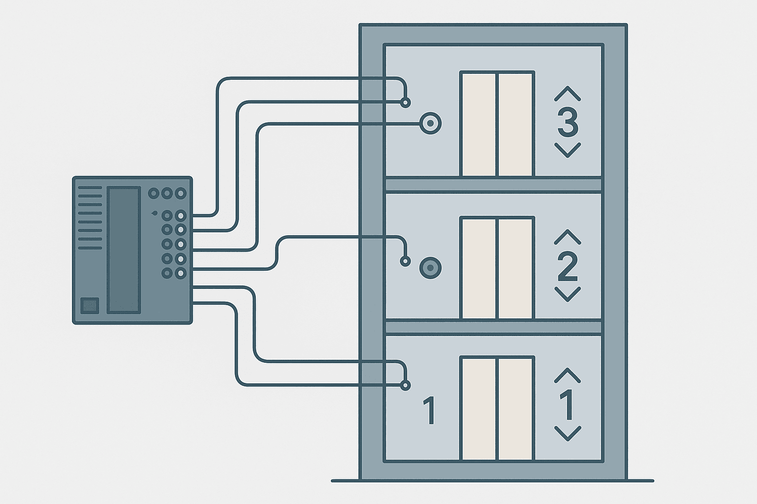
This exercise models a 3-floor, single-car elevator with one up/down call button per floor (6 buttons total), a limit switch at each floor, a door open/close timer, and a direction bit. The PLC platform is Rockwell Studio 5000 / Logix, but the logic translates directly to any IEC 61131-3 ladder environment. You do not need motion control or a drive for this exercise. A pair of relay outputs driving a small gearmotor in forward/reverse is enough to simulate it on a test rig or in software.
I/O List and Tag Definitions
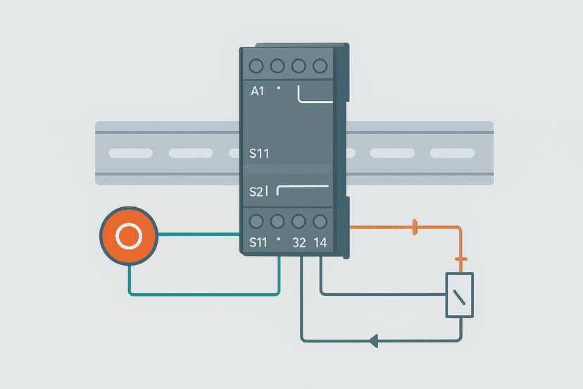
Keep the I/O tight. This is a training exercise, not a real elevator controller covered by EN 81-20, so you do not need safety-category wiring here. If you want to understand how safety inputs would layer on top, the concepts in Safety Relay Wiring: Circuits Explained apply directly.
| Tag | Type | Description |
|---|---|---|
| Btn_Call_F1_Up | BOOL Input | Floor 1 Up call button (momentary NO) |
| Btn_Call_F2_Up | BOOL Input | Floor 2 Up call button |
| Btn_Call_F2_Dn | BOOL Input | Floor 2 Down call button |
| Btn_Call_F3_Dn | BOOL Input | Floor 3 Down call button |
| LS_At_Floor1 | BOOL Input | Limit switch, car at floor 1 |
| LS_At_Floor2 | BOOL Input | Limit switch, car at floor 2 |
| LS_At_Floor3 | BOOL Input | Limit switch, car at floor 3 |
| Door_Closed | BOOL Input | Door closed feedback (NO contact) |
| Call_Latch_F1 | BOOL Internal | Latched call request for floor 1 |
| Call_Latch_F2 | BOOL Internal | Latched call request for floor 2 |
| Call_Latch_F3 | BOOL Internal | Latched call request for floor 3 |
| Dir_Up | BOOL Internal | Car travelling up |
| Dir_Dn | BOOL Internal | Car travelling down |
| Floor_Current | INT Internal | Current floor number (1/2/3) |
| Floor_Target | INT Internal | Requested destination floor |
| Motor_Up | BOOL Output | Hoist motor forward (up) |
| Motor_Dn | BOOL Output | Hoist motor reverse (down) |
| Door_Open_Sol | BOOL Output | Door open solenoid |
| Door_Timer | TON Internal | Door dwell timer (3 s preset) |
How the Logic Is Structured
Break the program into four clear rungs groups. Doing this before you write a single contact saves you an hour of untangling later.
- Call latching: Latch each floor call request when the button is pressed; unlatch when the car arrives at that floor.
- Current floor tracking: Update Floor_Current using the limit switches.
- Direction and target selection: Compare Floor_Current to the nearest pending call and set Dir_Up or Dir_Dn. This is where most beginners make mistakes.
- Door control: When the car arrives, stop the motor, open the door, run the dwell timer, then close the door and clear the latch.
Step 1: Latching the Floor Calls
Each floor call button is momentary. The instant the operator releases it, the input drops. You must latch it internally or the car will never know where to go. Use OTL/OTU pairs.
For floor 1: OTL(Call_Latch_F1) when Btn_Call_F1_Up goes true. OTU(Call_Latch_F1) when LS_At_Floor1 is true AND the door has opened (Door_Timer.DN). Apply the same pattern for floors 2 and 3. The unlatch condition is important: do not unlatch on arrival alone. Wait until the door timer completes, otherwise the car might re-register the same floor immediately on the next scan.
Step 2: Tracking the Current Floor
Use three MOV rungs. When LS_At_Floor1 is true, MOV 1 into Floor_Current. When LS_At_Floor2 is true, MOV 2. When LS_At_Floor3 is true, MOV 3. Floor_Current only updates while a limit switch is active, which is exactly what you want. Between floors, it holds the last known value.
Step 3: Direction and Target Selection (the Hard Part)
This is where the exercise earns its keep. You need to compare Floor_Current against the pending call latches and decide which direction to travel. For a 3-floor car with no directional preference algorithm, the simplest working rule is:
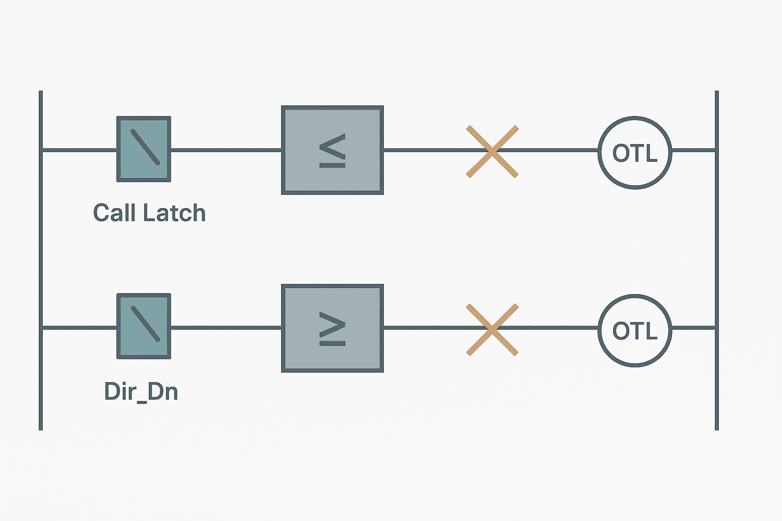
- If Call_Latch_F3 is true AND Floor_Current < 3, set Dir_Up.
- If Call_Latch_F1 is true AND Floor_Current > 1, set Dir_Dn.
- If Call_Latch_F2 is true AND Floor_Current < 2, set Dir_Up.
- If Call_Latch_F2 is true AND Floor_Current > 2, set Dir_Dn.
- Dir_Up and Dir_Dn must be interlocked: XIO(Dir_Up) on the Dir_Dn rung and vice versa.
In Studio 5000, use GRT (Greater Than) and LES (Less Than) compare instructions on the same rung as the call latch contact. For example: XIC(Call_Latch_F3) + LES(Floor_Current, 3) = OTL(Dir_Up). The XIO interlock on the same coil prevents Dir_Dn from being set at the same time.
Once Dir_Up or Dir_Dn is set, drive Motor_Up or Motor_Dn through an XIC contact on the direction bit, gated by XIO(LS_At_Floor3) for the up direction (do not drive up past the top floor) and XIO(LS_At_Floor1) for the down direction. Those limit switch interlocks are your crude overtravel protection.
Step 4: Door Control with a TON Timer
When the car arrives at a called floor, the sequence is: stop the motor, open the door, dwell for 3 seconds, close the door, clear the call latch. The TON handles the dwell. The Door_Closed feedback input re-enables motor operation.
The arrival condition is: the limit switch for the target floor is active AND the corresponding call latch is set. Tie both into the TON enable rung. Set PRE to 3000 ms. When Door_Timer.DN goes true, pulse OTU on the call latch and de-energise Door_Open_Sol. Add XIO(Door_Closed) to the Motor_Up and Motor_Dn rungs so the motor cannot run with the door open.
Ladder Rung: Elevator Door Dwell and Call Clear
Elevator Floor 2 Arrival: Door Timer and Call Latch Clear (Studio 5000). Ladder logic (5 rungs): Rung 0: examine if LS_At_Floor2 is on (XIC), then examine if Call_Latch_F2 is on (XIC), then examine if Door_Closed is off (XIO), then TON on Door_Timer. Rung 1: examine if LS_At_Floor2 is on (XIC), then examine if Call_Latch_F2 is on (XIC), then examine if Door_Closed is off (XIO), then energize output Door_Open_Sol (OTE). Rung 2: examine if Door_Timer.DN is on (XIC), then unlatch output Call_Latch_F2 (OTU). Rung 3: examine if Door_Timer.DN is on (XIC), then unlatch output Dir_Up (OTU). Rung 4: examine if Door_Timer.DN is on (XIC), then unlatch output Dir_Dn (OTU). When the car is at floor 2 with an active call latch and the door is not yet closed, the 3-second door dwell timer runs and the door solenoid is energised. When the timer completes, the floor call latch and both direction bits are unlatched, ready for the next call.
The diagram above evaluates one scan. Run these exact rungs on a real scan cycle to watch the latching and the timers behave.
Run this in the simulatorExtending the Exercise: Where to Go Next
Once the basic logic runs, push yourself with these additions:
- Directional preference: If the car is travelling up and a floor 2 call comes in while passing through floor 2 going to floor 3, should it stop? Add logic that checks whether the call direction matches the current travel direction before unlatching.
- Cabin buttons: Add three inputs simulating buttons inside the car (one per floor). These latch the same Call_Latch_Fx tags, so the cabin and hall calls share the same destination logic.
- Fault detection: Add a watchdog TON that trips if the car has been between floors for more than 15 seconds without hitting a limit switch. OTL a Motor_Fault bit and kill both motor outputs.
- HMI floor indicator: Write Floor_Current to an HMI integer tag and display it as a floor number. If you want to display direction arrows, map Dir_Up and Dir_Dn to bit indicators.
- Second car: Duplicate the entire program section for a second car on the same shaft. Now you need car-selection arbitration logic. That is a real scheduling problem.
Common Mistakes in This Exercise
| Mistake | Symptom | Fix |
|---|---|---|
| Unlatching the call on arrival, not on door close | Car leaves before door fully closes | Move OTU into the Door_Timer.DN rung |
| No interlock between Dir_Up and Dir_Dn | Both motor outputs energise, tripping a drive fault or blowing a fuse | Add XIO(Dir_Up) to every rung that sets Dir_Dn and vice versa |
| Missing overtravel limit on motor rungs | Car drives into end stop at floor 1 or floor 3 | Add XIO(LS_At_Floor1) to Motor_Dn rung; XIO(LS_At_Floor3) to Motor_Up rung |
| Floor_Current not initialised on first PLC power-up | Compare instructions behave unexpectedly on startup | Add a first-scan rung (using S:FS or FirstScan tag) that MOVs 1 into Floor_Current if LS_At_Floor1 is true, otherwise 0 |
| Door_Timer not reset after the car leaves | Timer accumulator carries over to next arrival | Add RES(Door_Timer) on a rung gated by XIO(LS_At_Floor2) so the timer resets when the car is not at floor 2 |
Running It Without Real Hardware
You do not need a physical rig to get value from this. Studio 5000 Logix Emulate lets you run the program and force inputs from the I/O tree. Set up a watch window with all the call latches, Floor_Current, Dir_Up, Dir_Dn, and Door_Timer.ACC visible at once. Then force Btn_Call_F3_Dn true for one scan, verify Call_Latch_F3 latches, then force LS_At_Floor3 true and watch the timer run. That single sequence exercises three of the four logic groups.
CODESYS users can do the same with the CODESYS SoftPLC and the built-in simulation mode. GX Works3 (Mitsubishi) has a simulator that handles TON and compare instructions without modification. The logic structure shown here is platform-agnostic: only the instruction names differ.
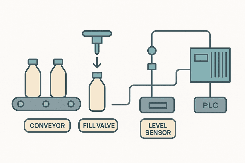
If you have already completed the PLC Bottle Filling Machine project, the elevator is a natural next step. The bottle filler gives you timer and counter fundamentals in a linear sequence. The elevator adds branching logic and state variables, which is where real production machines live.
What This Exercise Actually Teaches
By the time you have a 3-floor elevator running correctly, you have used OTL/OTU latches, TON timers, compare instructions, interlock logic, and an integer state variable. Those five tools cover the majority of real-world PLC programs. The elevator just packages them into a scenario that is easy to visualise and verify, which is why it has been a classroom staple for decades. The fact that it comes up in job interviews fairly often does not hurt either.
Frequently asked questions
What PLC instructions do I need for an elevator logic exercise?
How do I prevent the elevator motor from running with the door open?
Should I use an SFC (Sequential Function Chart) instead of ladder for elevator logic?
How do I handle two call requests at the same time in PLC elevator logic?
Can I simulate this elevator exercise without a real PLC?
How is the elevator exercise different from a simple start/stop motor rung?
Now build it
You have just read about OTL and XIO and OTU. Reading a rung and making one behave are different skills, and the second one is the job.
State Coil / Fault Coil
Intermediateabout 15 minA fault lamp that latches ON when any alarm condition occurs, even briefly, and only clears on Reset. And if the condition is still present when Reset is released, the fault comes right back.
Build this rungFree, no signup, runs in your browser. See all 16 exercises.
Was this helpful?