Safety Relay Wiring: Circuits Explained
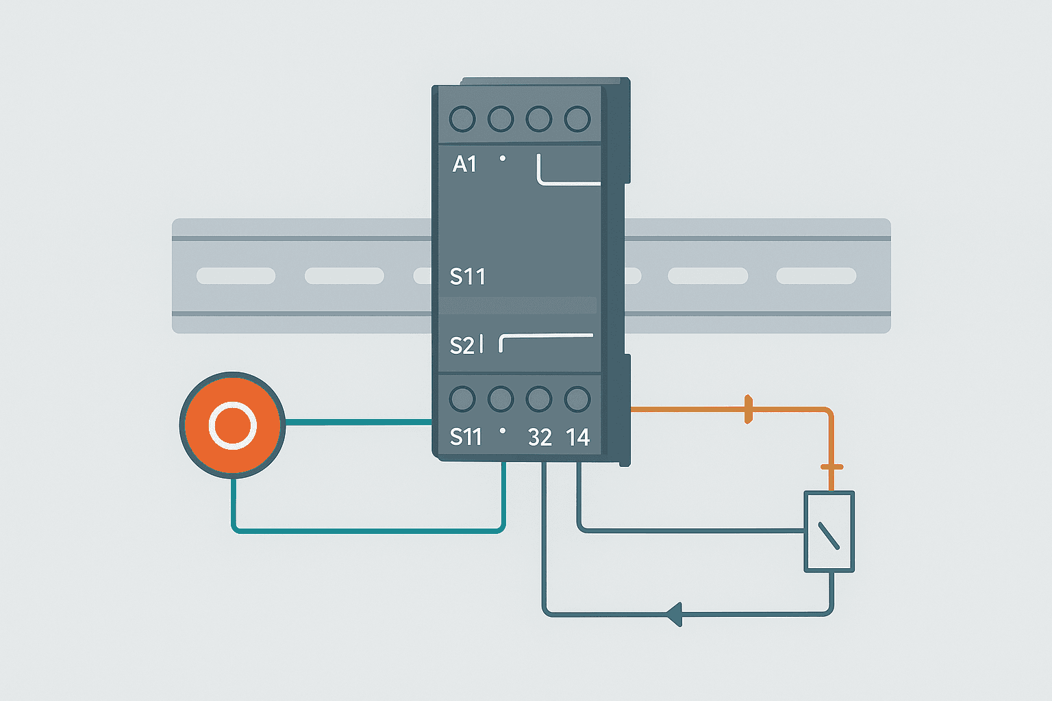
A safety relay is not a normal relay with extra marketing. It has forced-guided contacts, internal cross-fault monitoring, and a defined reset sequence. Wire it wrong and it either nuisance-trips constantly or, worse, fails silently and gives you a false sense of safety. This post walks through every terminal on a typical safety relay, shows you the canonical dual-channel E-stop circuit, and covers the three things that trip up most engineers: the feedback loop, the reset input, and how the safe outputs talk to a standard PLC input.
Why a Safety Relay Is Different from a Standard Relay
A standard relay has mechanically independent contacts. One contact can weld closed while another opens normally, and the relay has no way to detect that. A safety relay uses forced-guided (mechanically linked) contacts: if any normally-open contact welds shut, the normally-closed contacts are physically prevented from closing. The relay can therefore check its own contact state on every reset cycle.
Most safety relays also run an internal self-test on power-up and verify that both input channels open and close together within a defined time window (typically 0.5 s, though some devices let you configure this). A single-channel break or a cross-short between the two input channels is detected before the output is ever allowed to energise.
Terminal Map: What Every Pin Does
The example below uses the widely copied Pilz PNOZ X3 layout. Virtually every discrete safety relay on the market maps to the same concept, so learn this one and the others are just a different label font.
| Terminal | Label (PNOZ X3 style) | Function |
|---|---|---|
| A1 / A2 | Supply +24 VDC / 0 V | Relay coil supply. A1 is positive, A2 is negative/common. |
| S11 | Common for input channels | Switched 24 V fed to both E-stop contact chains. |
| S12 | Channel 1 return | One side of E-stop button contact 1 returns here. |
| S21 | Common for channel 2 (sometimes linked to S11) | Start of channel 2 path on some models. |
| S22 | Channel 2 return | One side of E-stop button contact 2 returns here. |
| S33 / S34 | Reset input | Momentary N/O reset pushbutton wired between S33 and S34 (or +24 V and S34 depending on model). |
| Y1 / Y2 | Feedback / EDM loop | External device monitoring: normally-closed auxiliaries of downstream contactors loop through here. Leave linked only if no external contactors are used. |
| 13 / 14 | Safe output 1 (N/O) | First pair of safety-rated output contacts. |
| 23 / 24 | Safe output 2 (N/O) | Second pair of safety-rated output contacts. |
| 33 / 34 | Safe output 3 (N/O) | Third pair, available on three-channel variants. |
| 41 / 42 | Auxiliary output (N/C) | Non-safety signalling contact, typically wired to a PLC input for status feedback. |
The Dual-Channel E-Stop Wiring Circuit
An E-stop button with two independent N/C contacts is the most common safety relay input. You wire each contact into a separate channel so the relay can detect a single contact failure or a wiring short. Here is how the circuit flows:
- +24 VDC from the safety relay's S11 terminal feeds out to the E-stop button.
- E-stop N/C contact 1 returns the signal to S12 (channel 1).
- E-stop N/C contact 2 returns the signal to S22 (channel 2).
- When both channels read 24 V simultaneously, the safety relay knows the E-stop is released and both contacts are healthy.
- Press the E-stop: both channels drop. The safety relay de-energises its output contacts within 10 ms or less.
- After the E-stop is released, the operator presses the manual reset button (momentary N/O, wired to S33/S34). The relay checks its feedback loop, confirms both channels are live, then re-energises the safe outputs.
The Feedback Loop (EDM): What It Is and When You Need It
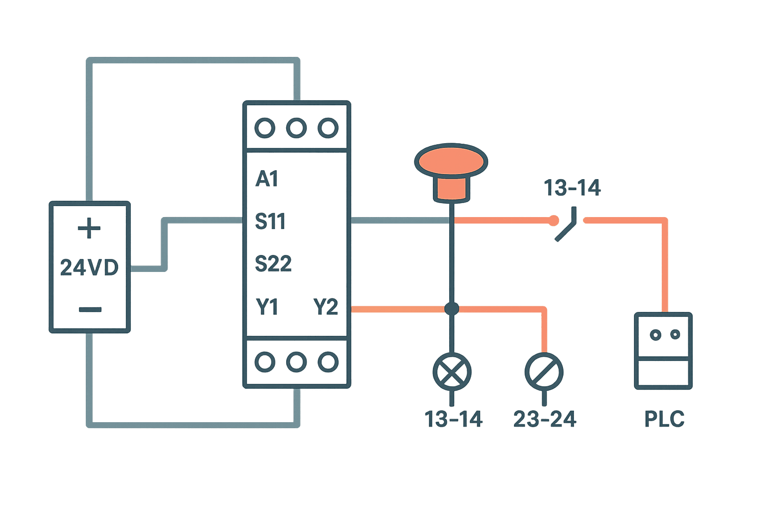
EDM stands for External Device Monitoring, sometimes called the feedback loop or Y1/Y2 terminals. The idea is simple: the safety relay watches the downstream contactors to confirm they actually de-energised when the safe outputs dropped. If a contactor welds closed, its N/C auxiliary contact stays open, so the Y1/Y2 loop stays open, and the safety relay refuses to reset.
To wire it: connect a wire from Y1 through the N/C auxiliary of every contactor in the safety circuit, then back to Y2. If you have two contactors in series (redundant switching, which is the right way to do it for Category 3 or 4), both N/C auxiliaries go in series in the feedback loop. When the contactors are de-energised their N/C auxiliaries are closed, the loop is complete, and reset is allowed.
Manual vs Automatic Reset: Choosing the Right Mode
Most safety relays support both reset modes, selected by a jumper or DIP switch.
| Mode | How It Works | When to Use It |
|---|---|---|
| Manual reset | Operator must press a momentary N/O pushbutton after the hazard is cleared. The relay checks channels and feedback before re-enabling outputs. | Any application where a person could be in the hazard zone: machinery guarding, E-stops, safety gates. Required for most Category 3 / PLd and above applications. |
| Automatic reset | Outputs re-energise as soon as the input channels close again, with no operator action. | Allowed only when the hazard disappears the moment the guard closes and no one can be inside. Light curtains on low-risk sensing applications sometimes use this, but get a risk assessment sign-off first. |
The reset button must be mounted outside the hazard zone, with a clear line of sight into it. A button inside the guarded area defeats the entire purpose. I have seen exactly this mistake on a robot cell that passed initial commissioning because nobody actually walked inside the cell during the safety check.
Connecting the Safety Relay to a Standard PLC
The safe output contacts (terminals 13/14, 23/24) must switch the power to your hazardous devices, usually the coils of two safety-rated contactors. They are not meant to carry the PLC's logic supply. The PLC does not directly control machine safety through these contacts, the safety relay does.
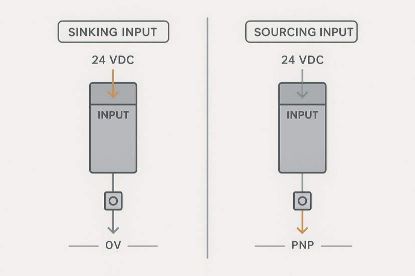
What the PLC does get is status feedback, usually from the N/C auxiliary output at terminals 41/42. Wire 41/42 to a standard PLC discrete input. When the safety relay is energised (machine safe to run), the N/C auxiliary is open, so the PLC input reads 0. When the relay trips, the N/C closes and the PLC input reads 1. You use this to suppress start commands, log faults, and drive HMI status indicators. For wiring that PLC input correctly see the notes on sinking vs sourcing I/O.
Light Curtain and Two-Hand Control Wiring Differences
The safety relay input topology stays the same, but the field device changes:
- Light curtain (OSSD outputs): The curtain controller outputs two 24 V PNP signals (OSSD1 and OSSD2) that pulse low periodically for self-testing. Wire OSSD1 to S12 and OSSD2 to S22. The safety relay must be rated for OSSD inputs, which most modern units are. Do not use a standard relay with OSSD signals because the test pulses will cause nuisance trips or go undetected.
- Two-hand control: Each hand button feeds one channel. Both must be pressed within 500 ms (IEC 60574-3 Type IIIC) for the relay to energise. The relay monitors simultaneous actuation, so releasing one hand de-energises the output immediately.
- Safety gate switch: A typical non-contact safety switch (e.g., Schmersal AZM300 or SICK i10) has two N/C output contacts, one per channel, exactly like an E-stop. Wire identically to the dual-channel E-stop circuit.
Common Wiring Mistakes and How to Avoid Them
- Shorting S11 to S12 and S22 with a jumper to test the relay: This bypasses the field device and makes the relay think the E-stop is released. Never do this in a commissioned panel, even temporarily.
- Using the safe output contacts to power a PLC input directly: The contacts are rated for contactor coil loads (typically up to 6 A at 230 VAC or 24 VDC). A PLC input draws milliamps. This is fine electrically, but it bypasses the dual-contactor redundancy the safety design likely requires. Route the PLC feedback through the auxiliary output instead.
- Long cable runs without considering voltage drop: If S11 feeds an E-stop button 50 m away, factor in cable resistance. A marginal 24 V supply that drops to 18 V at the button may cause the relay to read an intermittent fault. Use 1.5 mm2 cable for runs over 20 m.
- Mixing safety and non-safety wiring in the same conduit: EMI from motor cables can induce noise on the safety input channels. Keep them separated, or use shielded cable and ground the shield at one end only. The control panel grounding post covers this in more detail.
- Forgetting to test the feedback loop: Commissioning a safety circuit without defeating one contactor to verify the relay refuses to reset is not commissioning, it is hoping.
Achieving Category 3 PLd with a Single Safety Relay
A typical PNOZ X3 or MSR127 is certified to Category 4 PLe when wired correctly with redundant contactors and a feedback loop. For most machine guarding applications, Category 3 PLd is the target from the risk assessment. You get there with:
- Dual-channel input (two independent N/C contacts from the safety device).
- Two redundant output contactors with mechanically linked N/C auxiliaries in the feedback loop.
- Manual reset button located outside the hazard zone.
- Periodic proof-test interval documented in your safety plan (typically every 12 months for a manually operated E-stop, or whenever maintenance is performed).
For the SIL and PFHd numbers behind those performance levels, the IEC 62061 SIL levels explained post is a good companion read.
PLC Logic: Safety Relay Status and Reset Inhibit (Rockwell Studio 5000). Ladder logic (3 rungs): Rung 0: examine if SafetyRelay_Trip is on (XIC), then examine if Machine_Running is off (XIO), then latch output SafetyFault_Latch (OTL). Rung 1: examine if SafetyFault_Latch is on (XIC), then examine if Operator_FaultAck is on (XIC), then examine if SafetyRelay_OK is on (XIC), then unlatch output SafetyFault_Latch (OTU). Rung 2: examine if SafetyRelay_OK is on (XIC), then examine if SafetyFault_Latch is off (XIO), then energize output StartCmd_Permitted (OTE). Rung 1: Latches a safety fault in the PLC when the safety relay trips (N/C auxiliary closes, SafetyRelay_Trip=1) and the machine is not already stopped. Rung 2: Unlatches the fault only when the operator acknowledges AND the safety relay has successfully reset (SafetyRelay_OK=1 from the N/O auxiliary). Rung 3: Permits a machine start command only when the safety relay is healthy and no fault is latched. This does not replace the hardwired safety circuit; it adds operator-facing feedback and start inhibit logic in the standard PLC.
The diagram above evaluates one scan. Run these exact rungs on a real scan cycle to watch the latching and the timers behave.
Run this in the simulatorFrequently asked questions
Can I use a normal relay instead of a safety relay for an E-stop circuit?
What happens if I leave the Y1/Y2 feedback terminals linked with a jumper?
Do OSSD light curtain outputs wire to a safety relay the same way as E-stop contacts?
Can the safety relay output contact directly drive a VFD's STO input?
How often do I need to test a safety relay circuit once it is installed?
Learn this by building it
There is a PLC in this site. It runs a real scan engine, checks your logic against the same tests a working machine would fail, and needs no download and no account.
Open the exercisesFree, no signup, runs in your browser. See all 16 exercises.
Was this helpful?