Sinking vs Sourcing PLC I/O: Wiring It Right

Sinking and sourcing is one of those topics that trips people up once, they ask someone, they get a half-answer involving 'NPN' and 'PNP', and they walk away more confused than before. So let's sort it out properly, from the current-flow fundamentals up to real wiring decisions.
Sinking vs Sourcing: The One-Sentence Definition
A sinking input or output pulls current into the terminal. A sourcing input or output pushes current out of the terminal. That's it. The confusion comes from the fact that 'sinking' and 'sourcing' describe the module, while 'NPN' and 'PNP' describe the sensor, and you have to pair them correctly.
NPN vs PNP Sensors: What They Actually Do
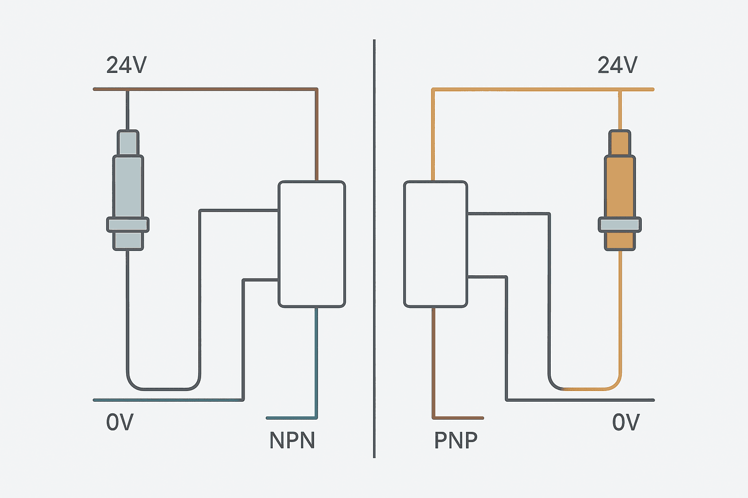
Almost every discrete sensor you'll wire in industrial automation is a three-wire DC type: brown to 24 VDC, blue to 0 V, and a black signal wire. The signal wire is either NPN or PNP output.
- NPN sensor (sinking output): When the sensor activates, the black signal wire connects internally to 0 V. Current flows from the load (the PLC input) into the sensor and out to common. The sensor sinks current.
- PNP sensor (sourcing output): When the sensor activates, the black signal wire connects internally to the 24 V supply. Current flows out of the sensor and into the load (the PLC input). The sensor sources current.
NPN is dominant in Japan and much of Asia. PNP is the default in North America and most of Europe. If you order a sensor without specifying output type and you're in the US, you'll almost certainly get PNP. In Japan, NPN. Know your region's default before you spec a project.
Sinking vs Sourcing Input Modules
Now for the PLC side. Input modules are described from the module's perspective, not the sensor's.
- Sinking input module: The input terminal is connected to the negative side of the detection circuit. To turn the input ON, you supply 24 V to the terminal from an external source (like a PNP sensor or a switch tied to 24 V). Current flows into the module's common, which is wired to 0 V. The module sinks the current.
- Sourcing input module: The input terminal is connected to the positive rail inside. To turn the input ON, you pull the terminal toward 0 V (like an NPN sensor or a switch tied to 0 V). Current flows out of the module. The module sources current.
Quick Reference Table
| Sensor Output | Sensor Action on Activation | Required PLC Input Module | Common at Module |
|---|---|---|---|
| PNP (sourcing) | Drives signal wire to +24 V | Sinking input | 0 V (COM to 0 V) |
| NPN (sinking) | Drives signal wire to 0 V | Sourcing input | +24 V (COM to 24 V) |
Sinking vs Sourcing Output Modules
Outputs work the same way but the load is now a relay coil, solenoid, indicator light or similar device instead of a sensor.
- Sourcing output module: When the output turns ON, the module drives the output terminal to +24 V. Current flows out of the terminal, through the load, and back to 0 V. Load is connected between the output terminal and 0 V.
- Sinking output module: When the output turns ON, the module drives the output terminal to 0 V (pulls it low). Current flows from +24 V through the load and into the terminal. Load is connected between +24 V and the output terminal.
In practice, sourcing outputs are more common in European and North American panels. Most Siemens S7-1200/1500 standard digital output modules are sourcing (P-switching). Most Mitsubishi Q/iQ-R modules default to sinking. Always check the datasheet before you wire. The wrong assumption here costs you a blown fuse or a coil that never energises.
Sinking Input Module Wiring: Step by Step
Here's how to wire a PNP sensor to a sinking input module, which is the most common setup in European and North American panels:
- Connect the sensor's brown wire to the +24 VDC supply terminal.
- Connect the sensor's blue wire to the 0 V (DC common) terminal.
- Connect the sensor's black signal wire to the PLC input terminal (e.g., I0.0 on an S7-1200).
- Connect the module's COM terminal to 0 V. On an S7-1200 standard DI module, the '1M' terminal is the common for the first group of 8 inputs, and it must go to 0 V for a sinking configuration.
- Apply power. When the sensor detects its target, it drives the signal wire to ~24 V, current flows into the module's COM and the input bit turns ON.
The 'Sink/Source' Selector Switch: When the Module Does Both
Many modern PLC families offer 'sink/source' or 'bidirectional' input modules that accept either NPN or PNP sensors on the same terminal. Allen-Bradley's 1769-IQ16 (CompactLogix) is a classic example. These modules have a built-in pull-up to 24 V and a pull-down to 0 V simultaneously, so both current directions are valid. They cost a bit more but they're a lifesaver on retrofit projects where you inherit a mix of sensor types and don't want to swap modules.
The Omron CJ2/CP2E series also has configurable commons per group for the same reason. Beckhoff EL1008 and similar EtherCAT terminals are sourcing-only (PNP sensors), so watch out if you're mixing in some older NPN devices on a TwinCAT system.
Real-World Gotchas You'll Actually Hit
- Sensor shows ON even when not triggered. You wired an NPN sensor to a sinking input module. The input is floating high via the module's internal pull-up. Fix: swap to a sourcing module, or fit a 4.7 kΩ pull-down resistor between the signal wire and 0 V (a temporary measure at best).
- Input never turns ON. PNP sensor, sourcing module, COM wired to 24 V instead of 0 V. The sensor is trying to push 24 V into a terminal already referenced to 24 V, so there's no voltage difference and the optocoupler doesn't fire. Wire COM to 0 V.
- Both inputs on a group stay OFF. You forgot to wire the group's COM terminal entirely. It's floating, there's no return path for current, nothing works. This is the most common commissioning mistake on first builds.
- Noise triggering inputs. Long cable runs with NPN sensors on sourcing modules can pick up noise because the signal line is pulled toward 0 V only by the sensor's transistor. Keep signal cables away from motor cables, use shielded cable on runs over 10 m, and ground the shield at one end only.
- Two-wire sensors with sinking or sourcing cards. Two-wire (load-powered) sensors have a leakage current of typically 0.5 to 1.5 mA even when OFF. Some PLC input modules have a low enough off-state threshold (as low as 2 mA) that this leakage current alone keeps the input ON. Always check the sensor's leakage spec against the module's off-state current threshold.
Which Should You Default To?
If you're designing a new panel in North America or Europe, default to PNP sensors and sinking input modules. It's the standard expectation, spare parts are easier to source, and field technicians will recognise the wiring immediately. In Asia, especially Japan, NPN with sourcing inputs is equally standard and you shouldn't fight it if your customer or machine builder expects it.
For outputs, sourcing (P-switching) is the safer default because a short to 0 V on the field wiring doesn't immediately fire the output coil. With a sinking (N-switching) output module, a short of the signal wire to 0 V turns the output ON regardless of the PLC command, which can be a safety concern on certain actuators. This isn't always critical, but it's worth knowing before you specify a project.
For panel wiring tips on protection components like fuses and breakers that protect these I/O circuits, see Fuse vs Breaker Selection for Control Panels.
A Ladder Rung That Depends on Getting This Right
Here's a simple interlock rung where a proximity sensor (PNP, wired to a sinking input) must be confirmed before a gate solenoid can open. The bit ProxSensor_At_Home only goes TRUE when the sensor is correctly wired and the module COM is tied to 0 V. If the wiring is wrong, the output GateSolenoid_Open never energises, no matter what the PLC program says.
Proximity Sensor Interlock for Gate Solenoid. Ladder logic: Rung 0: examine if ProxSensor_At_Home is on (XIC), then examine if Safety_Gate_Closed is on (XIC), then examine if Fault_Active is off (XIO), then energize output GateSolenoid_Open (OTE). The gate solenoid output energises only when the PNP proximity sensor confirms the part is home, the safety gate is confirmed closed, and no active fault is present. All three conditions depend on correctly paired sensor-to-module wiring. A sinking input module COM must be tied to 0 V for PNP sensors; if it is not, ProxSensor_At_Home will never go TRUE and the solenoid will never open.
The diagram above evaluates one scan. Run these exact rungs on a real scan cycle to watch the latching and the timers behave.
Run this in the simulatorFive-Minute Field Test
If you inherit a panel and don't know what sensor type is wired, do this before you change anything:
- Put a multimeter on DC voltage mode between the sensor's black signal wire and 0 V with the sensor NOT triggered. NPN output will read near 0 V. PNP output will read near 24 V (pulled up via the module's internal circuit).
- Trigger the sensor. NPN output will pull toward 0 V (stays near 0 V or drops lower). PNP output will pull toward 24 V (rises to near 24 V).
- Check the module's COM terminal voltage. COM at 0 V means sinking module expecting PNP sensors. COM at 24 V means sourcing module expecting NPN sensors.
- Cross-reference: sensor type matches module type? If yes, you're good. If not, you've found your wiring fault.
Frequently asked questions
What is the difference between a sinking and sourcing PLC input?
Can I connect an NPN sensor to a sinking input module?
Which is better: sinking or sourcing I/O?
How do I tell if a sensor is NPN or PNP without documentation?
What does it mean when a PLC input module is described as 'sink/source' or 'bidirectional'?
Why does my PLC input stay ON even when the sensor is not triggered?
Learn this by building it
There is a PLC in this site. It runs a real scan engine, checks your logic against the same tests a working machine would fail, and needs no download and no account.
Open the exercisesFree, no signup, runs in your browser. See all 16 exercises.
Was this helpful?