Emergency Stop Circuit Wiring: Categories Explained
An emergency stop button wired to a standard PLC input is not a safety function. Say that again at your next design review and watch heads turn. But it is true. ISO 13850 and ISO 13849 are clear: the e-stop circuit must be designed to a specific Performance Level, and that starts with understanding the three stop categories and what they demand from your wiring.
This post walks through how to actually wire an e-stop circuit for Categories 0, 1 and 2, what dual-channel monitoring means in hardware, and the gotchas that trip up even experienced engineers on their first safety audit.
Stop Categories Under IEC 60204-1
IEC 60204-1 (Machine Electrical Equipment) defines three stop categories. ISO 13850 (the e-stop standard) then says the emergency stop function shall use either Category 0 or Category 1. Category 2 is a controlled stop that retains power, so it is used for operational stops, not true emergency stops in most machinery applications.
| Stop Category | How Power Is Removed | Typical Hardware | Use for E-Stop? |
|---|---|---|---|
| Category 0 | Immediate, uncontrolled power removal to the actuator | Direct contactor drop-out, spring-return valve | Yes, most common |
| Category 1 | Controlled stop, then power removed after standstill | Drive STO after deceleration ramp, then contactor opens | Yes, where abrupt stop causes hazard |
| Category 2 | Controlled stop, power retained at standstill | Drive holds position at zero speed | No (not for e-stop per ISO 13850) |
The Emergency Stop Circuit: What the Hardware Actually Looks Like
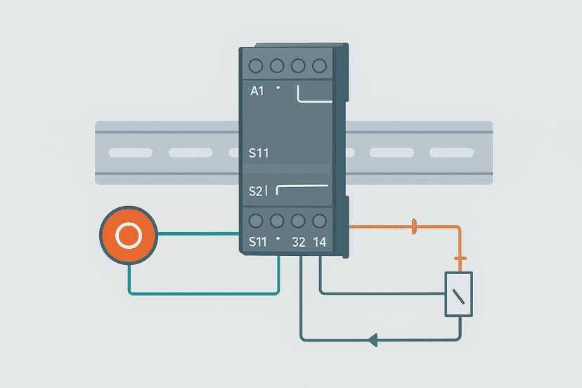
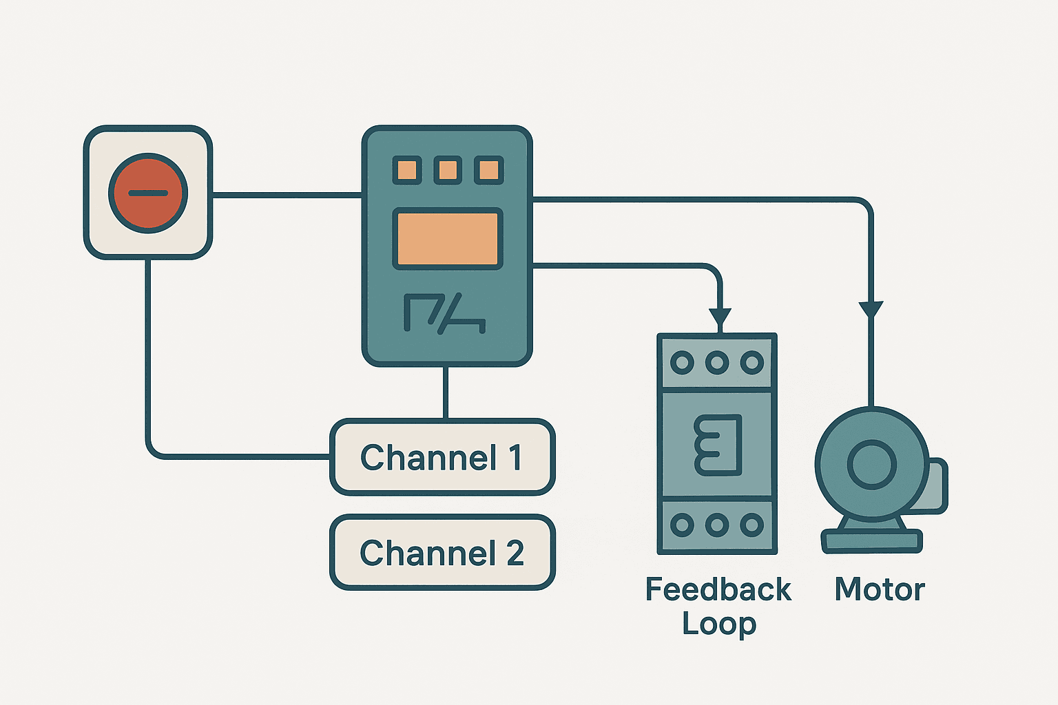
A properly wired e-stop circuit for PLd or SIL 2 has four distinguishing features: a normally-closed (NC) pushbutton with forced-operation contacts, dual-channel wiring, cross-fault monitoring between channels, and a monitored feedback loop. Here is what each of those means in practice.
NC Contacts with Forced Operation
Every e-stop button you buy must be direct-opening action (forced operation) to IEC 60947-5-1, Annex K. This means the NC contact is mechanically forced open by the actuator, not just spring-loaded. If the contact welds shut, the actuator physically separates it. Look for the symbol: a small diagonal bar through the contact symbol on the datasheet. Pilz, Schmersal, EUCHNER, and ABB all mark this clearly. If the datasheet does not show that symbol, the button is not suitable for a safety function.
Dual-Channel Wiring
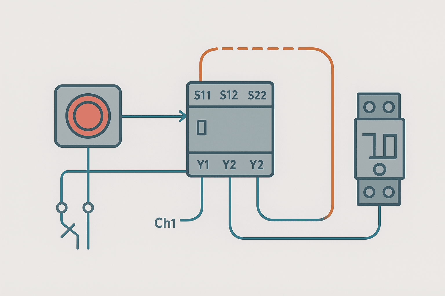
For PLd/PLe (ISO 13849) or SIL 2/3 (IEC 62061), you need two independent channels from the button to the safety relay. The button block has two separate NC contacts, each on its own wire pair, running to dedicated input terminals on the safety relay. Channel 1 goes to S11/S12 and Channel 2 goes to S21/S22 on a typical Pilz PNOZ X relay, for example. These channels run in separate conduit where practical. The reason is simple: a single wire chafing on a cabinet edge and shorting to ground should not defeat the safety function.
Cross-Fault Detection
A safety relay monitors the timing relationship between the two channels. When you press the button, both NC contacts should open within a few milliseconds of each other. If Channel 1 opens but Channel 2 stays closed for longer than the relay's discrepancy time (typically 0.5 s on a Pilz PNOZ X, configurable on a Pilz PNOZmulti), the relay latches in a fault state and will not allow a reset. This catches the scenario where one channel's wire is bridged to 24 VDC, keeping it permanently 'healthy' while the real button contact is the only thing breaking the circuit.
The Feedback Loop (EDM)
EDM stands for External Device Monitoring, and it is the most commonly omitted feature on non-compliant e-stop circuits. The safety relay's output contacts drive your main contactor coil (or contactors). Those same contactors have a NC auxiliary contact wired back to the Y1/Y2 feedback terminals on the safety relay. Before the relay allows a reset, it checks that the output contacts opened (i.e., the contactors dropped out). If a contactor welds and stays closed, the feedback loop stays open, and the safety relay will not reset. You cannot restart the machine until the fault is cleared.
On a Pilz PNOZ X2.8P, for instance, the wiring is: 24 VDC to A1, 0 VDC to A2, Channel 1 NC contact between S11 and S12, Channel 2 NC contact between S21 and S22, the contactor's NC auxiliary contact between Y1 and Y2 (with Y2 bridged to S12), and the relay's 13/14 and 23/24 safety output contacts in series with the contactor coil. That is a complete, auditable Cat. 4 / PLe circuit with a single button.
Emergency Stop Circuit Categories vs. Performance Level
People often confuse IEC 60204-1 stop categories with ISO 13849 architectural categories (Cat. B, 1, 2, 3, 4). They are different things. The stop category tells you how power is removed. The architectural category tells you how the circuit is structured to tolerate faults.
| ISO 13849 Category | Architecture | Fault Tolerance | Achievable PL |
|---|---|---|---|
| Cat. B | Single channel, no monitoring | None | PLa/PLb |
| Cat. 1 | Single channel, well-tried components | None | PLc |
| Cat. 2 | Dual channel with test by output | Some | PLc/PLd |
| Cat. 3 | Dual channel, any single fault does not cause loss of function | Single fault | PLd/PLe |
| Cat. 4 | Dual channel, faults detected, accumulation of undetected faults prevented | Single fault + detection | PLe |
Most industrial machinery targets PLd (equivalent to SIL 2). A dual-channel e-stop circuit with a properly certified safety relay, EDM feedback, and reset monitoring easily achieves Category 3 / PLd with high-quality components. Pushing to Category 4 / PLe typically requires the safety relay itself to have internal self-testing, which modern configurable safety controllers like the Pilz PNOZmulti 2 or Sick Flexi Soft handle natively.
Wiring Multiple E-Stop Buttons in Series
You can wire multiple e-stop buttons in series on each channel. If you have three stations, each station's button contributes one NC contact to Channel 1 and one NC contact to Channel 2. All Channel 1 contacts chain from S12 back toward S11, and all Channel 2 contacts chain from S22 back toward S21. The safety relay sees both channels as complete only when every button is released. This is the standard series wiring approach described in the keyword research and in most safety relay application manuals.
Category 1 Stop: Where a VFD Drive Fits In
A Category 1 stop is appropriate where an abrupt power cut causes a hazard: a high-inertia spindle that could snap tooling, or a vertical load that could drop. The sequence is: e-stop pressed, VFD decelerates the motor on its internal ramp (typically 0.5 to 5 seconds depending on your risk assessment), then the safety relay drops the output contactor and engages STO (Safe Torque Off) on the drive. STO is the drive's internal safety function that removes the PWM gate signals from the IGBT bridge without needing a contactor at all on modern drives certified to IEC 61800-5-2.
The practical wiring for a Category 1 stop with STO: the safety relay's output contacts drive both the run permissive to the drive and a timer output. On e-stop, the run permissive drops first (drive begins deceleration), and after the deceleration time, a second output or a time-delayed contact removes the STO enable. Many configurable safety relays like the Sick Flexi Soft or Pilz PNOZmulti 2 have configurable output delays built in, making this straightforward without adding external timing relays.
The Reset Button: Why It Must Be Monitored
ISO 13850 requires that the e-stop reset is a deliberate manual action and that it does not itself initiate a restart. The reset button must be a normally-open momentary contact wired to the safety relay's reset input. On the Pilz PNOZ X2.8P, that is the S33/S34 terminals. The relay latches after an e-stop and will only unlatch after: the button is released (both channels healthy), the EDM feedback confirms outputs are in the correct state, and then a positive rising edge on the reset input. A sustained high on the reset input (i.e., someone has jammed the reset button closed with a cable tie) will not allow a reset on a properly designed relay. This prevents defeating the function.
What the PLC Can and Cannot Do
The PLC sits outside the safety circuit for a basic hardwired e-stop design. It can monitor the safety relay's status output (a standard NO auxiliary contact) to know whether the machine is in an e-stop state. It can log timestamps, display alarms on the HMI, and inhibit its own outputs as a second layer. But it cannot be the primary means of removing power from the hazardous actuator. That path must be hardwired through the safety relay contacts.
If you are using a safety PLC (like a Siemens S7-1500F, Rockwell GuardLogix, or Beckhoff TwinSAFE), the safety logic runs in a certified partition of the CPU with its own watchdog, and the e-stop input wiring goes to a safety-rated I/O module. In that case the 'safety relay' is effectively implemented in software inside the safety PLC, but the hardware principles are the same: dual-channel input, discrepancy monitoring, EDM feedback, and a hardware safety output module that cuts the contactor. The PLC does not eliminate the dual-channel wiring requirement.
For more on how safety relay output monitoring feeds back into your PLC logic, the post on safety relay wiring circuits covers the auxiliary contact and status signal in detail. And if your risk assessment is pushing you toward SIL 2 quantification, IEC 62061 SIL levels explained gives you the underlying numbers framework.
Common Wiring Mistakes That Fail Safety Audits
- Wiring only one NC contact from a dual-contact button, leaving the second contact unused. You have a single-channel circuit, not dual-channel.
- Connecting both channels to the same wire pair. A single short takes out both channels simultaneously.
- Omitting the EDM feedback loop. The relay will reset even if a contactor has welded closed.
- Using a NO contact button instead of NC. If the wire breaks, the circuit appears healthy. NC contacts give you the fail-safe condition: open circuit equals e-stop active.
- Routing both channel cables through the same conduit with power wiring, causing induced noise that causes spurious trips or, worse, masks a real fault.
- Using a standard pushbutton without forced-operation contacts. Check for the IEC 60947-5-1 Annex K marking.
- Wiring the reset to a PLC digital output so operators can reset from the HMI. This is a compliance failure.
- Not testing the discrepancy fault condition during commissioning. Disconnect one channel and verify the relay latches and requires a reset before it will re-energize.
Quick Commissioning Checklist
- Verify button is NC, forced-operation type (check datasheet symbol).
- Confirm dual-channel wiring with each channel on a separate wire pair.
- With machine in a safe state, press the e-stop and verify both output contacts open (check with a multimeter across contactor coil terminals).
- Release the button and verify the relay does NOT auto-reset. Require a manual reset button press.
- Simulate a channel discrepancy fault by disconnecting one channel wire. Verify the relay latches and displays a fault.
- Simulate a welded contactor by disconnecting the EDM feedback loop. Verify the relay refuses to reset.
- Document all of the above in your machine's safety validation report. ISO 13849-1 requires documented validation testing, not just design.
Frequently asked questions
What is the difference between a Category 0 and Category 1 emergency stop?
What does the EDM feedback loop actually monitor?
Is a safety relay required, or can I use two standard relays in series?
Learn this by building it
There is a PLC in this site. It runs a real scan engine, checks your logic against the same tests a working machine would fail, and needs no download and no account.
Open the exercisesFree, no signup, runs in your browser. See all 16 exercises.
Was this helpful?