HMI Programming in TIA Portal: A Practical Guide
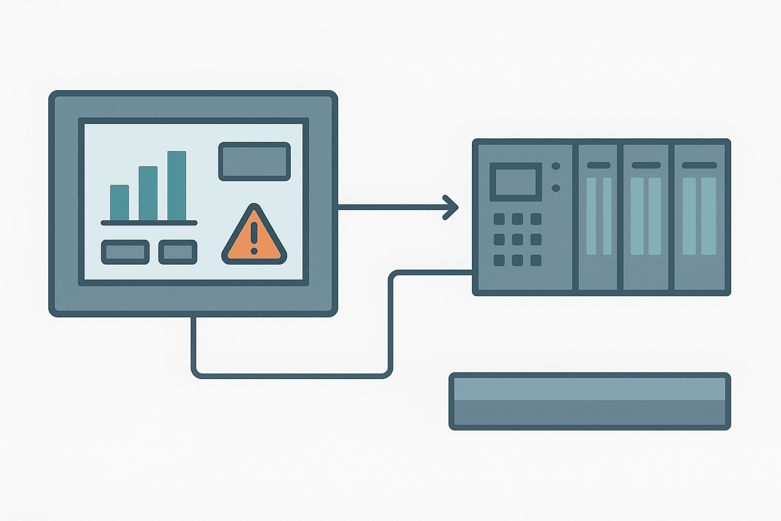
HMI programming in TIA Portal is one of those tasks that looks straightforward until you are three screens deep and realise your tag connections are broken, your alarm view scrolls off the bottom of the panel, and nobody told the operator which pump is actually running. This guide walks through the whole workflow on a Siemens KTP700 Basic (TP700 or KTP900 work the same way) integrated into a TIA Portal V17 project. The fundamentals apply to any WinCC Basic or WinCC Comfort panel.
HMI Programming vs PLC Programming: Know the Difference
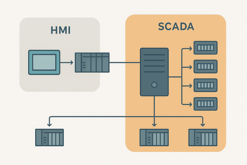
Your PLC holds the control logic. The HMI holds the visualisation and operator interaction layer. They share data through HMI tags, which are mapped to PLC memory addresses or symbolic tags. The HMI does not run ladder rungs. It polls the PLC over PROFINET (or MPI/PROFIBUS on older kit) and reads or writes values on a configured cycle. That polling cycle matters: set it too slow (2000 ms) and your trend curves look flat. Set every tag to 100 ms and a KTP700 will max out its CPU. A sensible starting point is 500 ms for displays and 200 ms for anything the operator uses to give a command.
Project Setup: Adding an HMI to an Existing TIA Portal Project
Open your TIA Portal project. In the device view, click "Add new device" and select your panel family under HMI. Pick the exact order number from the back of the panel (e.g., 6AV2 123-2GB03-0AX0 for a KTP700 Basic PN). TIA Portal will insert the panel into the network view and prompt you to run the HMI device wizard. Run it. It sets up the PROFINET interface IP, the PLC connection, and creates a default screen and alarm view automatically.
In the wizard, choose your S7-1200 or S7-1500 as the PLC connection partner. TIA Portal creates a "HMI_Connection_1" automatically and places both devices on the same PROFINET subnet. Give the HMI a fixed IP (e.g., 192.168.1.10 with subnet 255.255.255.0) that sits outside the DHCP range on your switch. Write that address on a label inside the panel door, because you will forget it at 2 AM during commissioning.
HMI Tags: Connecting Screens to PLC Memory
Navigate to the HMI tag table under your panel in the project tree. Every value you display or command from the screen needs an HMI tag. There are two kinds:
- External tags: mapped to a PLC tag or absolute address. Changes on screen write to the PLC. Changes in the PLC appear on screen after the next poll.
- Internal tags: live only in the HMI. Useful for navigation flags, local setpoints the operator enters before confirming, or screen-to-screen data you do not need in the PLC.
For external tags, click the "Connection" column and select your HMI connection. In the "PLC tag" column, browse to the symbolic tag in your S7 program, for example Pump1_Running (Bool) or Tank_Level_Pct (Real). TIA Portal copies the data type automatically. Do not use absolute addresses like M0.0 if you can avoid it. Symbolic tags survive a PLC memory reorganisation; absolute addresses do not, and tracking down why your running indicator shows the wrong pump at 6 AM is not a good time.
| HMI Tag Name | PLC Tag | Data Type | Acquisition Cycle | Use |
|---|---|---|---|---|
| Pump1_Running | Pump1_Running | Bool | 500 ms | Status indicator on overview screen |
| Tank_Level_Pct | Tank_Level_Pct | Real | 500 ms | Bar graph, level display |
| Setpoint_Temp | Setpoint_Temperature | Real | 1000 ms | Operator entry field |
| Fault_Active | System_Fault | Bool | 200 ms | Alarm trigger and banner |
| Cmd_Pump1_Start | Cmd_Pump1_Start | Bool | 200 ms | Start button momentary command |
| Screen_Nav_Flag | (internal) | Int | 100 ms | Internal: track active screen number |
Building Screens: Layout Rules That Survive Commissioning
Open the "Screens" folder under your panel. The wizard created a "Root screen" (the startup screen) and a template. The template is your global navigation bar. Put your plant logo, a clock, an alarm count badge and your navigation buttons in the template. Every screen inherits it. Changing one button in the template changes it everywhere. Ignore this and you will manually update 14 screens when the customer decides the nav bar should be on the bottom instead of the top.
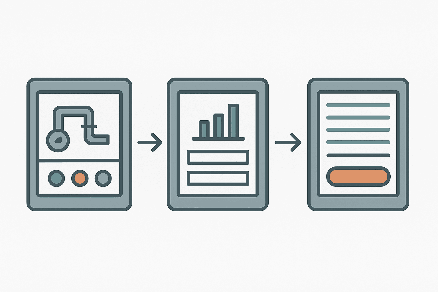
The Three Screens Every Panel Needs
- Overview screen: a simplified P&ID or equipment layout. Status colours (green running, grey stopped, red fault). No numbers here. Operators read symbols faster than text under pressure.
- Detail screen (one per major device or zone): actual values, setpoints, manual/auto mode switch, start/stop buttons. Keep it to one topic per screen.
- Alarm screen: dedicated view showing active and historical alarms. The wizard creates this automatically. Do not hide it behind two navigation taps.
Connecting Objects to Tags
Drop a circle on the overview screen to represent Pump 1. Right-click it and open "Properties". Under "Animations" add a "Appearance" animation. Set the background colour to green when Pump1_Running equals 1, and grey when it equals 0. Add a second animation layer for red when Fault_Active equals 1. Fault takes visual priority, so put it last in the list. That order matters: TIA Portal applies animations top-to-bottom and the last matching condition wins.
For a numeric display, drop an "IO field" from the toolbar. Set the tag to Tank_Level_Pct, mode to "Output" (display only), format pattern to 999.9, and suffix to %. For an operator entry field that writes back to the PLC, set mode to "Input/Output" and add a high/low limit so the panel rejects nonsense values before they reach your setpoint register. A tank level setpoint that accepts 9999.9% will cause you problems eventually.
Navigation Buttons and Screen Switching
Drop a button onto the template. In its "Events" tab, select the "Click" event and add the system function "ActivateScreen". Browse to the target screen. That is the entire navigation setup. No scripting required for basic screen changes. Where people go wrong is creating 30 individual navigation buttons and then needing to change the screen names halfway through the project. Use a consistent naming convention from day one: Scr_Overview, Scr_Pump1_Detail, Scr_Alarms. The underscore prefix groups them in the project tree and makes the ActivateScreen function call self-documenting.
HMI Alarm Configuration in TIA Portal
TIA Portal distinguishes between two alarm types you will use on almost every project:
- Discrete alarms: triggered by a Bool tag going TRUE. One tag, one alarm. Configure in HMI > HMI alarms > Discrete alarms. Set the trigger tag, alarm class (Error, Warning, System), alarm text and whether acknowledgement is required before the alarm clears from the active list.
- Analog alarms: triggered when a Real or Int tag crosses a high or low limit. Useful for tank overflow warnings or temperature exceedances without extra Bool flags in the PLC.
For the alarm text, include what failed and what to do, not just what the value is. "Tank 1 High Level" is acceptable. "Tank 1 Level > 90%, check inlet valve V1" is useful. The operator who reads it at shift handover will thank whoever wrote the second version. Alarm classes control colour and acknowledge behaviour. The default "Errors" class is red and requires acknowledgement. "Warnings" is yellow and auto-clears when the condition goes away. Set these in HMI > Alarm classes.
The alarm view control on your alarm screen shows active alarms by default. Add a second alarm view set to "Historical" mode so operators can scroll back and see when an alarm first appeared. Set the history buffer to at least 512 entries. On a KTP700, that is stored in the panel's internal flash. If you need the alarm log to survive a panel power cycle and be accessible remotely, you need a Comfort panel with a USB log or a SCADA system sitting above it.
Transferring the HMI Project to the Panel
Compile the HMI device first (right-click the panel in the project tree, "Compile" > "Software (rebuild all)"). Fix all errors before attempting a download. Warnings about unused tags are fine to leave. Errors about missing tag connections will crash the runtime on the panel, which manifests as a blank screen with a "Configuration error" message that tells you nothing useful.
Download via PROFINET using the same Ethernet port the panel uses for PLC communication. In "Go online" select the panel device. TIA Portal will find it by IP if you are on the same subnet. Use a direct PC-to-panel cable or put both on the same switch. The download takes 30 to 90 seconds on a KTP700 depending on project size. The panel reboots after download and the runtime starts automatically. You do not need a separate HMI programming cable on modern PN panels, which is a common question from engineers used to older Siemens panels that required a dedicated RS-422 cable.
Common HMI Programming Mistakes and How to Avoid Them
- All tags set to 100 ms acquisition: the panel's communication load spikes and some values update erratically. Tier your cycles: 200 ms for commands, 500 ms for displays, 1000 ms for setpoints.
- No screen template used: every global change (company logo, nav bar colour) becomes a 30-screen manual edit job.
- Alarm text says only the fault name: "Pump 1 Fault" tells the operator nothing. Add a cause and a first action.
- Input fields with no limits: an operator types 9999 into a setpoint that expects 0 to 100. The PLC clamps it, but only if you programmed that clamp. The HMI should reject it first.
- Forgetting to compile before download: TIA Portal sometimes allows downloading a stale build. You end up running yesterday's config and debugging a problem that was already fixed.
- Using absolute PLC addresses in HMI tags: reorganising PLC memory silently breaks every display that used absolute addresses. Always use symbolic tags.
Quick Checklist Before Handover
- All external HMI tags compile without errors and are connected to the correct PLC tags.
- Acquisition cycles are tiered, not all set to minimum.
- The screen template carries navigation, clock and alarm count badge.
- Every alarm has a meaningful text with cause and first action.
- Input fields have engineering unit limits configured.
- The alarm screen is reachable in one tap from any screen.
- The panel IP is labelled inside the door.
- You have done a full power-cycle test: panel off, panel on, verify runtime restarts and reconnects to PLC within 10 seconds.
- Historical alarm log buffer is at least 512 entries.
Frequently asked questions
What is HMI programming and how does it differ from PLC programming?
What software do I need for Siemens HMI programming?
How do I connect an HMI tag to a PLC tag in TIA Portal?
Why is my Siemens HMI showing a blank screen or configuration error after download?
Do I need a special cable to program a Siemens KTP700?
Learn this by building it
There is a PLC in this site. It runs a real scan engine, checks your logic against the same tests a working machine would fail, and needs no download and no account.
Open the exercisesFree, no signup, runs in your browser. See all 16 exercises.
Was this helpful?