PROFINET IO: Controller, Device and AR Explained
Most engineers use PROFINET every day without thinking too hard about what is actually happening under the hood. You drop an ET 200SP into your TIA Portal project, assign a device name, set an update time and it works. But the moment something goes wrong, or you need to squeeze cycle time out of a motion axis, or you are integrating a third-party device with a GSDML file that has forty configuration options, you need to understand the model underneath. That model is the IO Controller/Device architecture and the concept of an Application Relation (AR).
PROFINET IO: Three Roles on Every Network
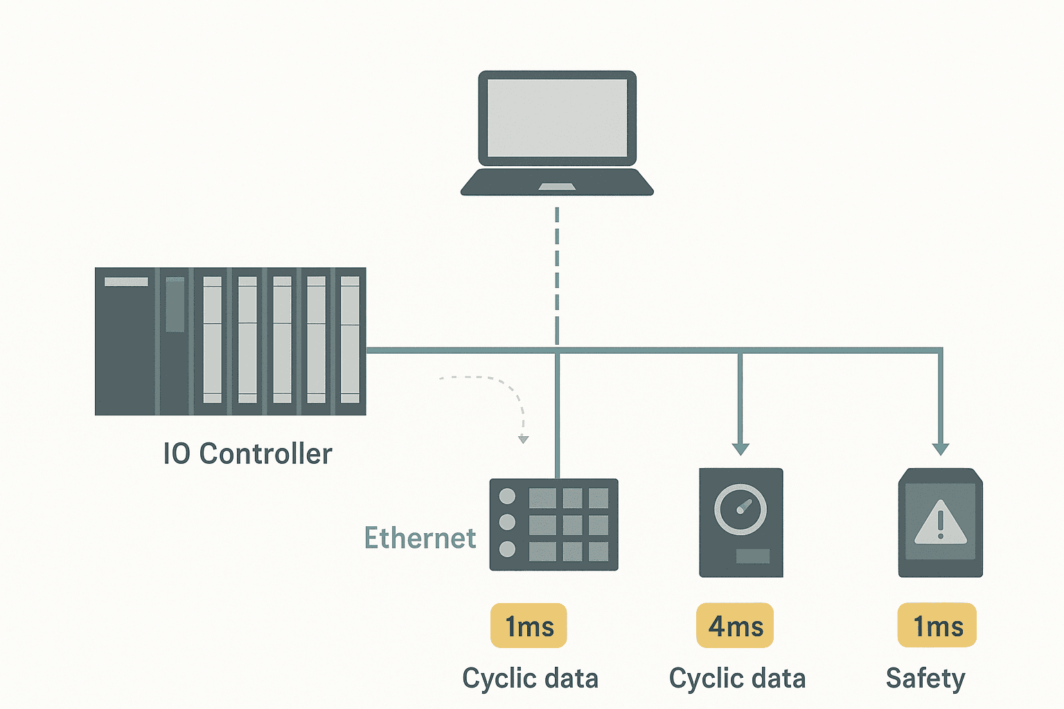
PROFINET IO defines three node roles. Every device on the network is exactly one of them at any given moment.
| Role | Typical hardware | What it does |
|---|---|---|
| IO Controller | S7-1200, S7-1500, S7-300/400 with PN interface, CODESYS runtime with PN master | Owns the cyclic process data exchange. Reads inputs from IO Devices, writes outputs to IO Devices. Establishes and maintains the AR. |
| IO Device | ET 200SP, ET 200MP, G120 drive with PN option, third-party remote IO, safety modules | Passive endpoint. Responds to the Controller's requests. Can also send alarm notifications (acyclic channel). |
| IO Supervisor | TIA Portal engineering station, Siemens PRONETA, commissioning laptop | Acyclic only. Used for parameterisation, diagnostics and commissioning. Never owns process data. |
One physical device can hold multiple roles simultaneously. A CPU 1515 with two PN interfaces can be an IO Controller on one interface and an IO Device (I-Device) on the other, feeding data up to a higher-level controller. That is the I-Device feature, and it shows up a lot in machine-builder architectures where a sub-machine needs to expose a clean IO interface to a cell controller.
What Is an Application Relation (AR)?
An AR is the logical connection between a Controller and a Device. Think of it as a contract: the Controller says "I will send you outputs every X ms and expect your inputs back in the same cycle", and the Device agrees to hold up its side. The AR is established during startup through a sequence of acyclic connect, write and application-ready messages. Once that handshake completes, cyclic exchange begins.
If the AR drops, the IO Device goes into fail-safe output mode: every output is held at its parameterised substitute value (usually zero, but you can set it per module in TIA Portal). The Controller sees a diagnostic alarm and, if you have not masked it, a red X on the device in the project tree. This is the mechanism behind every PROFINET station fault you have ever seen.
Communication Relations Inside an AR
Inside each AR there are three types of Communication Relation (CR), each serving a different purpose.
- IO CR (cyclic): carries process data at the configured update time. This is the fast path. Data travels as UDP/IP multicast (RT Class 1) or as a scheduled Ethernet frame (IRT). The Controller sends output data and the Device replies with input data in the same cycle.
- Record Data CR (acyclic): used for parameterisation, diagnostics and identification. Runs over standard TCP/IP. Slower, but reliable. This is how TIA Portal writes module parameters at startup, and how you read diagnostic records with SFB52/RDREC.
- Alarm CR (acyclic): lets the Device push unsolicited alarm notifications to the Controller. Process alarms, diagnostic alarms, pull/plug alarms all travel here. The Controller acknowledges each alarm; unacknowledged alarms queue in the Device.
PROFINET RT vs IRT: Choosing Your Real-Time Class
This is where PROFINET IO gets into real engineering territory. There are two real-time transmission classes that matter in practice.
| Class | Full name | Mechanism | Typical cycle time | Use case |
|---|---|---|---|---|
| RT | Real-Time (Class 1/2) | Prioritised Ethernet frames, VLAN tag with priority 6. Standard managed or unmanaged switches work. | 1 ms to 512 ms (configurable) | Standard remote IO, drives, distributed periphery. Most projects never need anything faster. |
| IRT | Isochronous Real-Time (Class 3) | Time-synchronised scheduled slots. Requires IRT-capable switches (e.g. Siemens SCALANCE X-200 IRT, X-300 IRT). Uses PTCP time sync. | 250 µs to 1 ms, jitter < 1 µs | Servo motion, high-speed printing, synchronised multi-axis. You pay for the switches. |
For 95% of projects, RT at 1 ms to 4 ms is plenty. IRT is genuinely needed for coordinated servo motion where axis-to-axis jitter has to stay under a microsecond. Don't spec IRT switches into a conveyor project just because someone read a datasheet. The SCALANCE XC-200 IRT switches run about three times the cost of a plain managed switch.
PROFINET IO Update Time: What You Are Actually Configuring
In TIA Portal, when you right-click a PROFINET device, go to Properties and look at the "Advanced options" for real-time settings, you see the "Update time" field. This is the IO CR cycle time: how often the Controller sends output data and expects input data back. The options are powers of two from 250 µs up to 512 ms, though the range available depends on the CPU and the device.
A common mistake is setting every device to 1 ms because it sounds fast. Every device at 1 ms increases the Controller's PN stack load. On an S7-1500 this is usually fine, but on an older S7-300 PN CPU you can easily overload the communication processor and get watchdog faults. Match the update time to what the application needs. A temperature sensor on a slow process? 32 ms or 64 ms is fine. A high-speed press brake with PROFINET servo drives? 1 ms or less.
Device Names and Device Numbers: Both Matter
Every PROFINET IO Device has two identifiers that the Controller uses.
- Device name: a human-readable string like
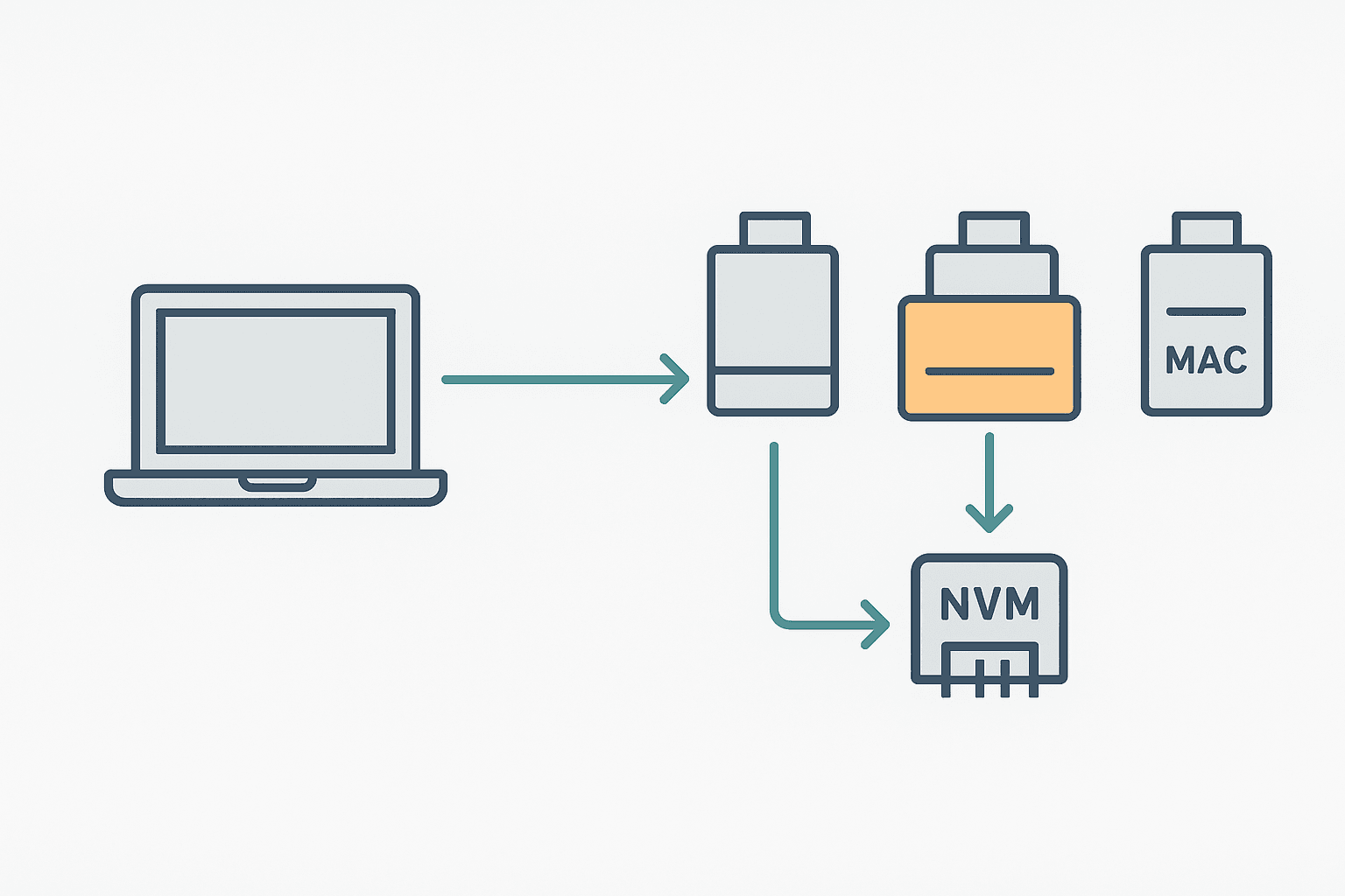
et200sp-conveyor-1. The Controller uses DCP (Discovery and Configuration Protocol) to assign this name to a physical device by MAC address during commissioning. The name is stored in the device's non-volatile memory. On startup, the Controller broadcasts a DCP Identify request, finds the device by name, and establishes the AR. - Device number: a 16-bit integer (1 to 2047) assigned in the TIA Portal project. Used internally for addressing. You rarely need to touch it, but it appears in diagnostic records and in the S7 diagnostic buffer.
The device name is case-insensitive and follows DNS hostname rules: lowercase letters, digits and hyphens, no underscores. This trips people up constantly. You type ET200SP_Line1 in TIA Portal, it silently converts to et200sp-line1, and then you try to set the name manually with a third-party tool using the underscore version and nothing matches. Always use hyphens.
GSDML Files: The Device Description You Cannot Ignore
Every PROFINET IO Device is described by a GSDML file (Generic Station Description Markup Language). It is an XML file that tells the engineering tool exactly what slots the device has, what IO data each slot produces or consumes, what parameters are configurable and what alarms it can generate. TIA Portal uses it to build the hardware catalog entry and to generate the correct AR configuration.
When you add an ET 200SP or a G120 drive from the TIA Portal hardware catalog, the GSDML is already embedded. When you add a third-party device, you install the GSDML manually via "Options > Manage general station description files". Use the exact version that matches your firmware. A GSDML mismatch between the file version and the physical firmware version is one of the most common reasons an AR fails to establish on a fresh commissioning, and TIA Portal's error message is not always helpful.
Configuring a PROFINET IO Device in TIA Portal: The Key Steps
- Add the CPU to the project and open the Network view.
- Drag the IO Device from the hardware catalog (or install its GSDML first for third-party devices). Connect it to the CPU's PN interface by dragging the green network line.
- Double-click the device to open its Device view. Add the correct module types to each slot to match the physical hardware.
- In Device Properties > General, assign the device name. Match it exactly to what you will write to the physical device using TIA Portal's "Assign device name" function.
- In Device Properties > PROFINET interface > Advanced options > Real time settings, set the update time appropriate for your application.
- Note the I/O addresses TIA Portal assigns automatically. You can change them, but keep them inside the default process image area for simple projects.
- Compile and download the hardware configuration. Then use Online > Accessible devices to assign the device name to the physical hardware by MAC address.
Step 7 is where most commissioning problems live. The physical device must have a blank or matching name before assignment works. If it already has a different name from a previous project, you have to reset it first. On an ET 200SP you can do that through TIA Portal's assign-name dialog: it lists all devices on the subnet and lets you reset and reassign.
Reading PROFINET Diagnostics in the PLC Program
Beyond ladder rungs and the HMI alarm list, you can interrogate PROFINET AR status programmatically. On S7-1500, the system data type LADDR and the instruction DeviceStates (in the Extended Instructions > Diagnostics library) let you read the status of every IO Device in the network from within your OB. The return value is a DWORD bitmask where each bit corresponds to a device number.
For deeper diagnostics, RDREC (SFB52 on S7-300/400, a standard instruction on S7-1500) reads a specific record from a device by its record index. Index 0x8000 gives you the diagnosis data for a module slot. This is how you find out not just that a device is offline, but which specific channel on which slot has a wire break or short circuit. It is the same data that appears in the hardware diagnostics view, but you can log it to a data block and ship it to a SCADA system.
PROFINET IO vs EtherNet/IP: A Quick Structural Comparison
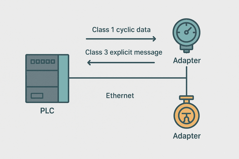
Both protocols run on standard Ethernet hardware at RT class, but they use fundamentally different models. EtherNet/IP uses the Common Industrial Protocol (CIP) and an implicit/explicit messaging split. PROFINET uses the AR/CR model described above. The practical difference for a PLC programmer is that EtherNet/IP Scanner-Adapter terminology maps roughly to PROFINET Controller-Device, but the configuration process, the real-time mechanism and the diagnostic channel work very differently. If you are working across both platforms, the post EtherNet/IP Scanner vs Adapter: How It Works is worth reading alongside this one.
Common PROFINET IO Mistakes and How to Avoid Them
- Wrong update time on all devices: setting 1 ms everywhere loads the PN stack. Use 4 ms or 8 ms for non-time-critical devices.
- Device name with underscores: the DCP protocol converts underscores to hyphens. Always use hyphens in your naming convention from the start.
- GSDML version mismatch: the file version must match the device firmware. Download the GSDML from the manufacturer's website for the exact firmware version on your hardware.
- Unmanaged switch in an IRT network: IRT requires managed, IRT-capable switches. An ordinary unmanaged switch will silently break IRT synchronisation.
- Forgetting substitute values: when the AR drops, outputs go to their substitute values. On a valve that defaults to open, this can be a safety issue. Check every output module's substitute value configuration before commissioning.
- Duplicate device names on the subnet: two devices with the same name fight for the AR. The Controller connects to whichever responds first. Use a naming convention that includes the line, machine and slot number, and document it.
Frequently asked questions
What is the difference between a PROFINET IO Controller and an IO Device?
What is a PROFINET Application Relation (AR)?
What update time should I use for PROFINET IO devices in TIA Portal?
Why does my PROFINET device name not match after I download the configuration?
Do I need special switches for PROFINET?
What is a GSDML file and where do I get it?
Learn this by building it
There is a PLC in this site. It runs a real scan engine, checks your logic against the same tests a working machine would fail, and needs no download and no account.
Open the exercisesFree, no signup, runs in your browser. See all 16 exercises.
Was this helpful?