PROFINET Wiring: Cables, Connectors and Topology
PROFINET runs on standard Ethernet hardware, which sounds like it should make wiring simple. In practice, the cable category, connector type, installation class and topology all matter a lot more than they do with office Ethernet. Get any of them wrong and you will spend a commissioning day chasing intermittent faults that vanish the moment you look at them. This guide covers what you actually need to know before you pull the first cable.
PROFINET Cable Types: What the Categories Actually Mean
The PROFINET standard (IEC 61784-5-3) defines four installation categories. Most panel builders only stock Category A and B, which covers the vast majority of applications.
| Category | Application | Max Segment Length | Cable Construction |
|---|---|---|---|
| Cat A | Fixed installation in cable ducts, conduit, trays | 100 m | 4-wire, shielded, solid conductor, AWG 22 |
| Cat B | Occasional flex, drag chains with low cycle count | 100 m | 4-wire, shielded, stranded conductor, AWG 22 |
| Cat C | Continuous flex, drag chains, robotic arms | 100 m | 4-wire, shielded, fine stranded, AWG 22 |
| Cat D | Single-pair, 2-wire (future use, not yet common) | Varies | 2-wire, shielded |
Category A cable is what Siemens sells as 6XV1840-2AH10 (sold by the metre) and what most panel shops keep on a drum. It's a shielded, 4-conductor, 100 Ohm impedance cable. The conductors are colour-coded: orange/white-orange for TX pair, blue/white-blue for RX pair, following the TIA-568B wiring scheme. That 4-wire construction supports 100 Mbit/s full-duplex. PROFINET IRT at 100 Mbit/s is what almost every S7-1200, S7-1500 and ET200SP installation runs.
RJ45 vs M12 Connectors: Which One to Use
PROFINET uses two connector families in the field. You'll pick based on the IP rating and environment, not personal preference.
RJ45 (IE FC RJ45)
The standard choice for anything inside a control panel or in a clean, dry environment. Siemens' Industrial Ethernet Fast Connect (IE FC) RJ45 plug (6GK1901-1BB10-2AA0) uses a push-pull locking collar to stop cables pulling out accidentally. That collar is not optional on a machine that vibrates. A plain office RJ45 without a locking collar will work electrically but will eventually walk itself loose.
The IE FC plug is designed for tool-free termination of Category A cable using a built-in IDC mechanism. Strip the outer jacket 35 mm, fan out the pairs, push into the connector body and crimp the shield clamp. The whole process takes about 90 seconds once you've done it a few times. The critical step is making sure the foil shield makes solid contact with the metal collar of the plug body. That shield connection is your EMC return path.
M12 D-coded (IP65/IP67)
Use M12 D-coded connectors anywhere the cable exits into a wet or washdown area, or anywhere an RJ45 port on the device itself would be exposed to moisture. ET200SP and ET200MP modules with M12 ports are common on food and beverage lines. The D-coded M12 pinout for PROFINET is standardised:
| Pin | Signal | Wire Colour (TIA-568B) |
|---|---|---|
| 1 | TX+ | Orange/White |
| 2 | RX+ | Green/White |
| 3 | TX- | Orange |
| 4 | RX- | Green |
PROFINET Wiring Topology: Line, Star and Ring
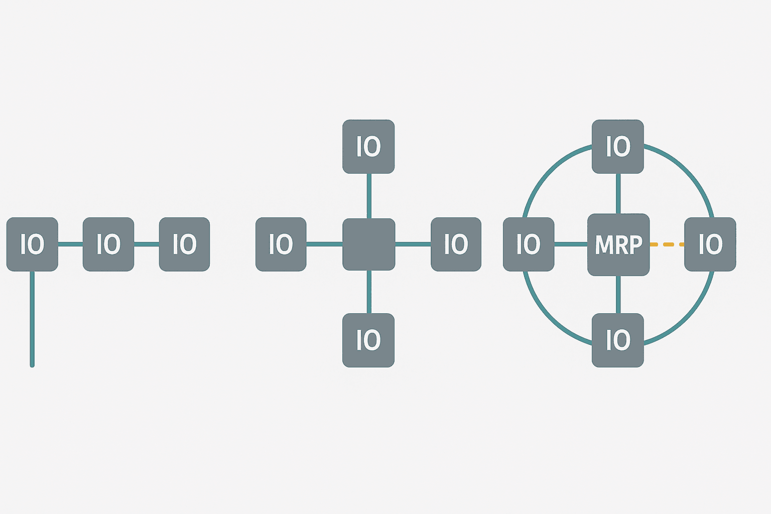
PROFINET is a standard Ethernet network, so it supports the same physical topologies. The topology you choose has a direct impact on fault tolerance and troubleshooting difficulty.
Line (Daisy-Chain)
This is the most common topology on a production line. Each device has a 2-port internal switch, so the PROFINET frames pass through the device from one port to the next. Siemens ET200SP, ET200S and many Siemens drives have this built in. The advantage is minimal cabling cost. The risk is that one failed device or cable break kills all downstream devices. For a 10-node line, losing node 4 kills nodes 5 through 10. That's acceptable on many lines but not on high-availability systems.
Star
Every device runs a separate cable back to a central PROFINET switch. This is more cable but isolates faults cleanly. One device or cable going down does not affect anything else. Use a managed switch (Siemens SCALANCE X series, Hirschmann, or similar) so you can monitor port status and media redundancy. An unmanaged consumer switch is not suitable for PROFINET IRT because IRT requires precise timestamping and forwarding that only managed switches support.
Ring with Media Redundancy Protocol (MRP)
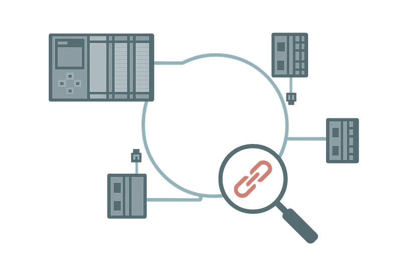
MRP is PROFINET's built-in ring redundancy protocol. You wire the devices in a ring, designate one managed switch as the MRP manager, and the manager blocks one port to prevent a loop. If a cable or device fails, the manager opens that port within 200 ms (or 30 ms on fast mode), and the network reconverges. MRP requires all devices in the ring to support the MRP client role, which is worth checking in the device's GSD file before committing to this topology. S7-1200 and S7-1500 CPUs support MRP manager and client. ET200SP supports MRP client.
Maximum Segment Length and Distance Rules
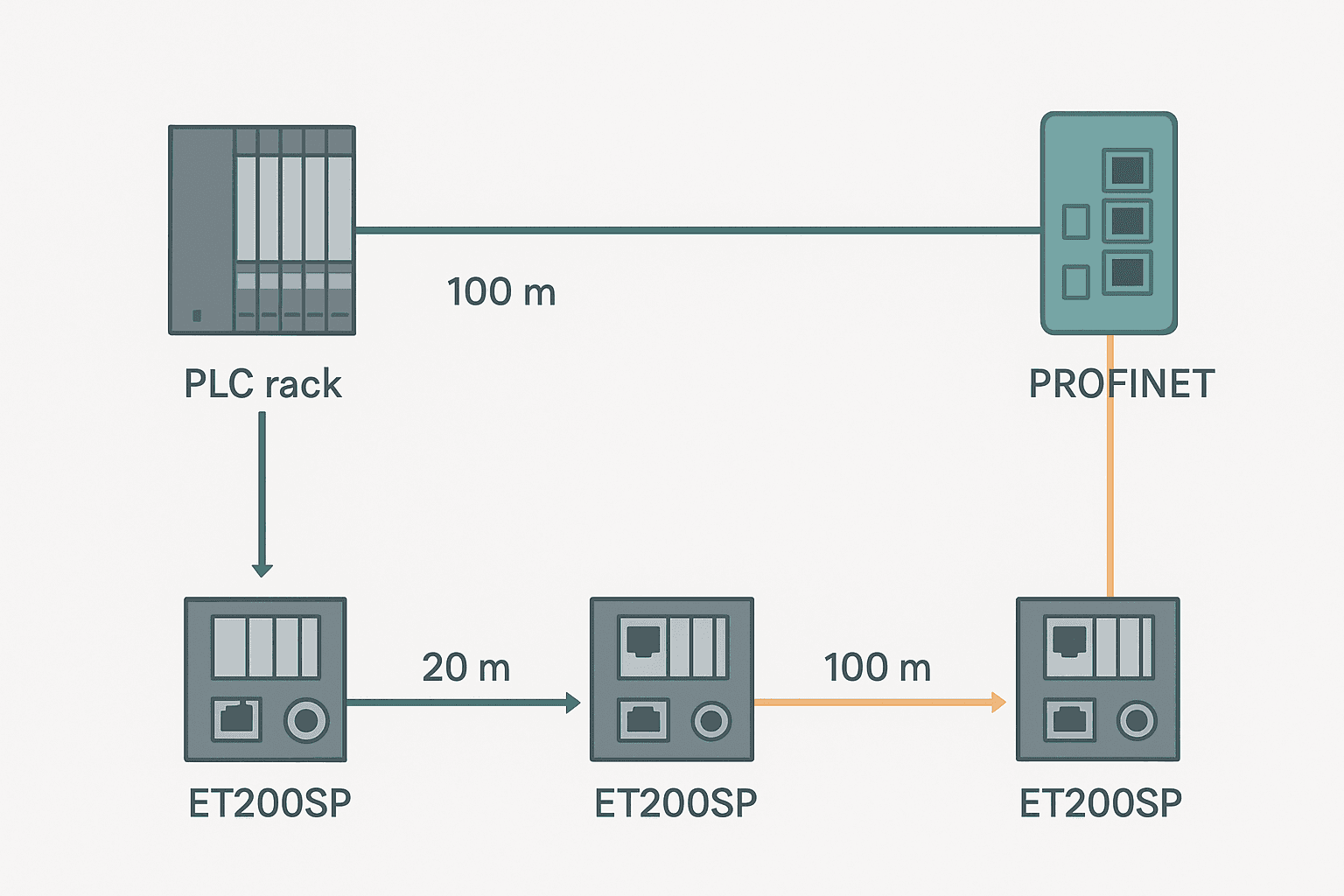
The 100 m limit per segment is a hard limit set by the 100BASE-TX standard, not a guideline. It counts from connector face to connector face, including any patch leads inside the panel. A 98 m field run plus a 4 m panel patch lead is 102 m and will cause random CRC errors, especially at temperature extremes when cable attenuation increases. Measure actual cable runs, not drawing dimensions.
If you need to go further than 100 m, add a managed switch at the mid-point. The switch regenerates the signal, and you start a fresh 100 m segment from there. Fibre optic runs can go up to 3000 m per segment using SC or LC connectors with Siemens SCALANCE X208 or similar media converters, but that's a different discussion.
Shielding, Grounding and EMC: The Part Everyone Gets Wrong
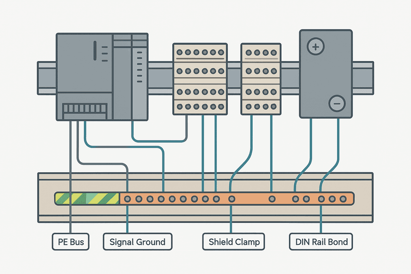
PROFINET cable must be shielded, and that shield must be terminated at both ends to the protective earth (PE). This is different from the advice sometimes given for fieldbus cables like Profibus DP, where single-end shield grounding was recommended to avoid ground loops. With PROFINET, the IEC 61784-5-3 standard requires both-end shield grounding because the shield is part of the EMC strategy for radiated emissions, not just noise rejection.
In practice, this means your IE FC RJ45 plug's shield clamp must grip the cable foil tightly, and the RJ45 socket on the device must be bonded to the device's PE connection. On an ET200SP mounted on a grounded DIN rail, this is automatic. For devices mounted on non-conductive surfaces, you need an explicit PE bond from the device housing to panel PE.
Bend Radius and Drag Chain Considerations
Category A cable with solid conductors must not be bent sharply. The minimum static bend radius is 8 times the outer cable diameter. For a typical 6 mm OD cable, that's 48 mm. In a drag chain, use Category C cable with fine-stranded conductors and a minimum dynamic bend radius of 10 times the outer diameter. Running Cat A cable in a drag chain will cause conductor fatigue cracks within months on a high-cycle machine. The fault will typically show up as an intermittent CRC error count that climbs slowly over weeks.
Also keep PROFINET cables out of the same conduit or trunking as power cables, especially VFD output cables. VFD output cables carry high dV/dt switching transients that couple capacitively into anything running alongside them. Minimum separation is 20 cm for parallel runs, or use a grounded metal separator. For short crossings, 90-degree crossing is fine.
Commissioning Checks Before You Go Live
- Verify cable continuity and wiring order with a cable tester before connecting to any live equipment. A crossed TX/RX pair will usually still link at 10 Mbit/s auto-negotiation but will fail at 100 Mbit/s.
- Confirm all shield connections have continuity from cable foil to device housing to PE rail.
- Check segment lengths against your cable schedule, not the drawing, especially if the cable was routed around obstacles.
- In TIA Portal, run the 'Accessible Devices' scan under Online and Diagnostics to confirm every device is visible before assigning IP addresses.
- After going online, monitor the PROFINET diagnostic buffer in TIA Portal for any CRC errors, port alarms or topology changes during the first 30 minutes of operation with all machines running.
- For MRP rings, perform a deliberate cable disconnection test to verify reconvergence and check that the MRP manager logs the event correctly.
If you're already past commissioning and chasing a live PROFINET fault, the post on PROFINET Communication Loss: How to Diagnose It covers the diagnostic workflow in detail, including how to read the PROFINET diagnostic buffer and interpret station error codes.
Quick Reference: PROFINET Wiring Rules
| Parameter | Rule / Value |
|---|---|
| Cable type | Shielded, 4-wire, 100 Ohm, Cat A/B/C per IEC 61784-5-3 |
| Max segment length | 100 m (RJ45 to RJ45 or M12 to M12) |
| Speed | 100 Mbit/s full-duplex (most PROFINET IO devices) |
| Connector, panel/dry | IE FC RJ45 with locking collar |
| Connector, wet/IP65+ | M12 D-coded 4-pin |
| M12 Pin 1 | TX+ (orange/white) |
| M12 Pin 2 | RX+ (green/white) |
| M12 Pin 3 | TX- (orange) |
| M12 Pin 4 | RX- (green) |
| Shield grounding | Both ends, to PE |
| Min static bend radius | 8x cable OD (Cat A/B) |
| Min dynamic bend radius | 10x cable OD (Cat C, drag chain) |
| Separation from power cables | Min 20 cm parallel, 90-degree crossing acceptable |
| Switch type | Managed (required for IRT and MRP) |
Frequently asked questions
Can I use regular Cat6 Ethernet cable for PROFINET?
What is the maximum cable length for a PROFINET segment?
What is the difference between M12 D-coded and A-coded connectors for PROFINET?
Does PROFINET cable shield need to be grounded at both ends?
What cable should I use in a drag chain for PROFINET?
Do I need a managed switch for PROFINET?
Learn this by building it
There is a PLC in this site. It runs a real scan engine, checks your logic against the same tests a working machine would fail, and needs no download and no account.
Open the exercisesFree, no signup, runs in your browser. See all 16 exercises.
Was this helpful?