24 VDC Power Supply Sizing for Control Panels
Undersizing a 24 VDC power supply is one of those mistakes that doesn't always show up during commissioning. The machine runs fine in the shop, ships to site, gets cold-started on a January morning with every solenoid energising at once, and the PSU trips on overload. You spend two hours on-site troubleshooting what was really a desk calculation that never got done properly.
This post walks through the full sizing process: tallying real loads, applying temperature derating, accounting for inrush, choosing between single and redundant supplies, and picking a unit that will actually last. All the numbers you need to do this in your next panel build.
Why 24 VDC Power Supply Sizing Actually Matters
Most 24 VDC PSUs on DIN rail (Phoenix Contact QUINT, Puls PIANO, Siemens SITOP, Murrelektronik MCA) are rated at 40 degrees C ambient. Run them hotter and the available output current drops. Push them above their rated current and the internal protection kicks in: either the output voltage sags, the unit goes into hiccup mode, or it trips and latches off. In a live machine that's a hard stop and a confused operator.
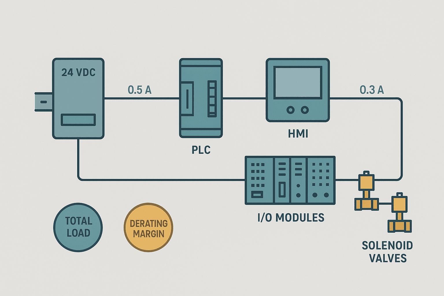
The calculation itself isn't complex, but it has to be systematic. Engineers who guess often guess low, or they pick the next size up from the nameplate PLC draw and forget that 16 solenoid valves, a remote I/O station, and a stack of safety relays add another 4 A on top.
Step 1: Build a Complete 24 VDC Load List
Go through the panel BOM and the electrical drawings and list every device that draws 24 VDC. Don't rely on memory. Common categories:
- PLC CPU and backplane (check the spec sheet; a CompactLogix 5380 CPU draws roughly 0.8 A from the backplane supply, but the I/O modules add more)
- Digital input modules (typically 5-10 mA per active input, so 16 inputs at 10 mA = 0.16 A)
- Digital output modules (load-dependent; add the actual output device current here, not just the module draw)
- Analog input and output modules (usually 50-150 mA per module)
- Remote I/O stations over PROFINET or EtherNet/IP (an ET 200SP head station plus 8 modules can pull 1.5 A or more)
- Solenoid valves (a Festo or SMC valve coil at 24 VDC is typically 0.3 to 0.6 A each; 8 valves = up to 4.8 A)
- Safety relays and safety PLCs (a Pilz PNOZ draws around 0.04 A standby but factor in the output contacts driving 24 VDC loads)
- HMI if 24 VDC powered (a Siemens KTP700 Basic draws about 0.35 A)
- Indicator lamps and tower lights (LED types are 0.02 to 0.05 A each; incandescent are much higher, avoid them)
- Fieldbus power injectors, switches, and any 24 VDC fans inside the panel
Step 2: Separate Continuous Loads from Inrush Loads
Solenoid valve coils have an energise inrush that can be 5 to 10 times the steady-state holding current for the first 20 to 50 milliseconds. Contactors and relays are similar. If you have a machine that power-cycles 12 solenoids simultaneously on a machine start signal, that inrush spike is real and it hits the PSU output capacitors hard.
Premium PSUs like the Phoenix Contact QUINT 4 and Puls PIANO series have a built-in peak current capability, typically 1.5 to 2 times rated current for up to 5 seconds. That handles solenoid inrush cleanly. Budget PSUs with no overload reserve will sag or trip under the same condition. Check the overload characteristic curve in the datasheet, not just the headline ampere rating.
Step 3: Apply Temperature Derating
Most DIN-rail PSUs are rated at full output up to 40 degrees C, then derate linearly to zero output at 60 or 70 degrees C. A panel in an unair-conditioned building in summer can see 50 degrees C internal temperature easily, especially when the VFDs, power resistors, and transformers in the same enclosure are throwing heat.
The derating factor is usually linear. For a PSU rated 10 A at 40 degrees C and 0 A at 70 degrees C, at 55 degrees C the available current is:
Available A = 10 × (1 - (55 - 40) / (70 - 40)) = 10 × (1 - 0.5) = 5 A
That's half the nameplate rating. A panel designed for 8 A continuous load with a 10 A PSU will fail in that environment. Check the derating curve for your specific model. Phoenix Contact publishes them clearly in the QUINT datasheets; Puls includes them in the PIANO series documentation.
Step 4: Add a Sizing Margin
After you have total continuous load and you've applied derating, add a margin. My personal rule is 25% minimum on the derating-adjusted figure. This covers:
- Future I/O expansion (customers always ask for more outputs 6 months after delivery)
- Loads you missed or whose draw was understated in the BOM
- PSU output voltage tolerance effects on downstream loads
- Component aging: electrolytic capacitors inside the PSU lose capacitance over years, reducing transient response
Worked Example: Sizing a 24 VDC Supply for a Mid-Size Panel
Here's a realistic panel inventory and how the numbers stack up.
| Device | Qty | Draw per Unit (A) | Total (A) |
|---|---|---|---|
| CompactLogix 5380 CPU + backplane | 1 | 0.85 | 0.85 |
| 1769 digital input module (16ch) | 2 | 0.12 | 0.24 |
| 1769 digital output module (16ch, no load) | 2 | 0.08 | 0.16 |
| 1769 analog input module (4ch) | 1 | 0.10 | 0.10 |
| SMC SY5000 solenoid valve coils (holding) | 12 | 0.35 | 4.20 |
| ET 200SP station (head + 8 modules) | 1 | 1.50 | 1.50 |
| Siemens KTP700 Basic HMI | 1 | 0.35 | 0.35 |
| Pilz PNOZ m B0 safety base unit | 1 | 0.10 | 0.10 |
| LED tower light (3 stack) | 1 | 0.12 | 0.12 |
| 24 VDC panel cooling fan | 1 | 0.25 | 0.25 |
| **Total continuous load** | **7.87** |
Total continuous load: 7.87 A. Now apply derating. Say the panel sits in a 45 degrees C environment; with a PSU rated full output to 40 degrees C and zero at 70 degrees C, at 45 degrees C the derating factor is (70 - 45) / (70 - 40) = 0.83. So the adjusted available output of a 10 A PSU at that temperature is 8.3 A. That gives you only 0.43 A of headroom, which is not enough.
Apply the 25% margin to the raw load: 7.87 × 1.25 = 9.84 A. At 45 degrees C, a 10 A PSU gives 8.3 A available, which still doesn't cover it. Step up to a 20 A PSU. At 45 degrees C it gives 16.6 A available, and 9.84 A sits comfortably within that at 59% loading. That's a good operating point: not so lightly loaded that the PSU runs inefficiently, not so heavily loaded that any single addition pushes it over.
Redundant 24 VDC Power Supplies: When You Actually Need Them
For high-availability machines, two PSUs in parallel with a diode ORing module (or a PSU with built-in redundancy like the Phoenix Contact QUINT POWER with selectivity module) give you N+1 redundancy. If one unit fails, the other carries the full load without any interruption.
The catch: both PSUs need to be sized for the full load on their own, not half each. And the ORing diode drops about 0.5 to 0.7 V, so you might need to trim the PSU output voltage up slightly to compensate. Some modern PSU models use active ORing MOSFETs instead of diodes, which keeps the drop under 0.1 V. Worth the extra cost on critical systems.
Redundancy is worth specifying when: the machine runs 24/7 with no acceptable downtime, the consequence of a PSU failure is a safety or quality incident, or replacing a PSU requires a long lead time for the end user. For a two-shift automated assembly line, it's often justified. For a simple conveyor in a factory with a spare PSU on the shelf, it's probably overkill.
Choosing the Right PSU: Specs That Actually Matter
Beyond ampere rating and derating, here's what separates a good PSU from a cheap one in industrial service:
- Hold-up time: how long the output stays within spec after AC input is lost. 20 ms is the minimum for riding through a momentary grid dip. 100 ms is better. Cheap units are often 10 ms or less.
- Output ripple and noise: specified in mV peak-to-peak. For analog signal circuits, lower is better. Aim for under 50 mV ripple. See the analog wiring posts if you're feeding 4-20 mA loops from the same rail.
- Short-circuit behaviour: hiccup mode (tries to restart periodically) is fine for most loads. Constant current mode is better if you have capacitive loads that need sustained current to charge.
- Diagnostics: signalling contact or LED for DC OK status. Wire this to a PLC input so you get an alarm before anything fails. The Phoenix Contact QUINT series has a floating contact; the Puls PIANO has an alarm relay output.
- MTBF: reputable vendors publish this. 500,000 hours at 40 degrees C is a reasonable benchmark for a quality unit.
Fusing the 24 VDC Distribution
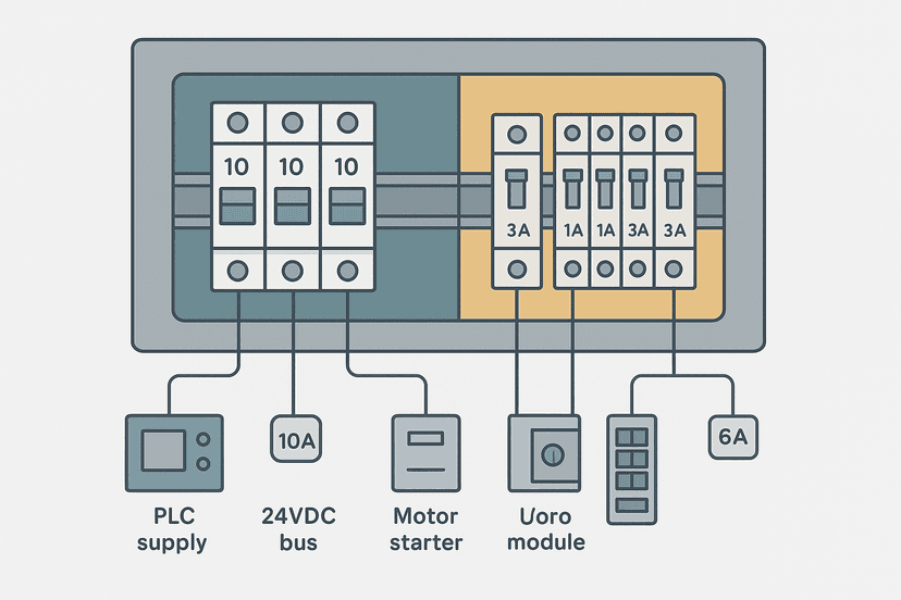
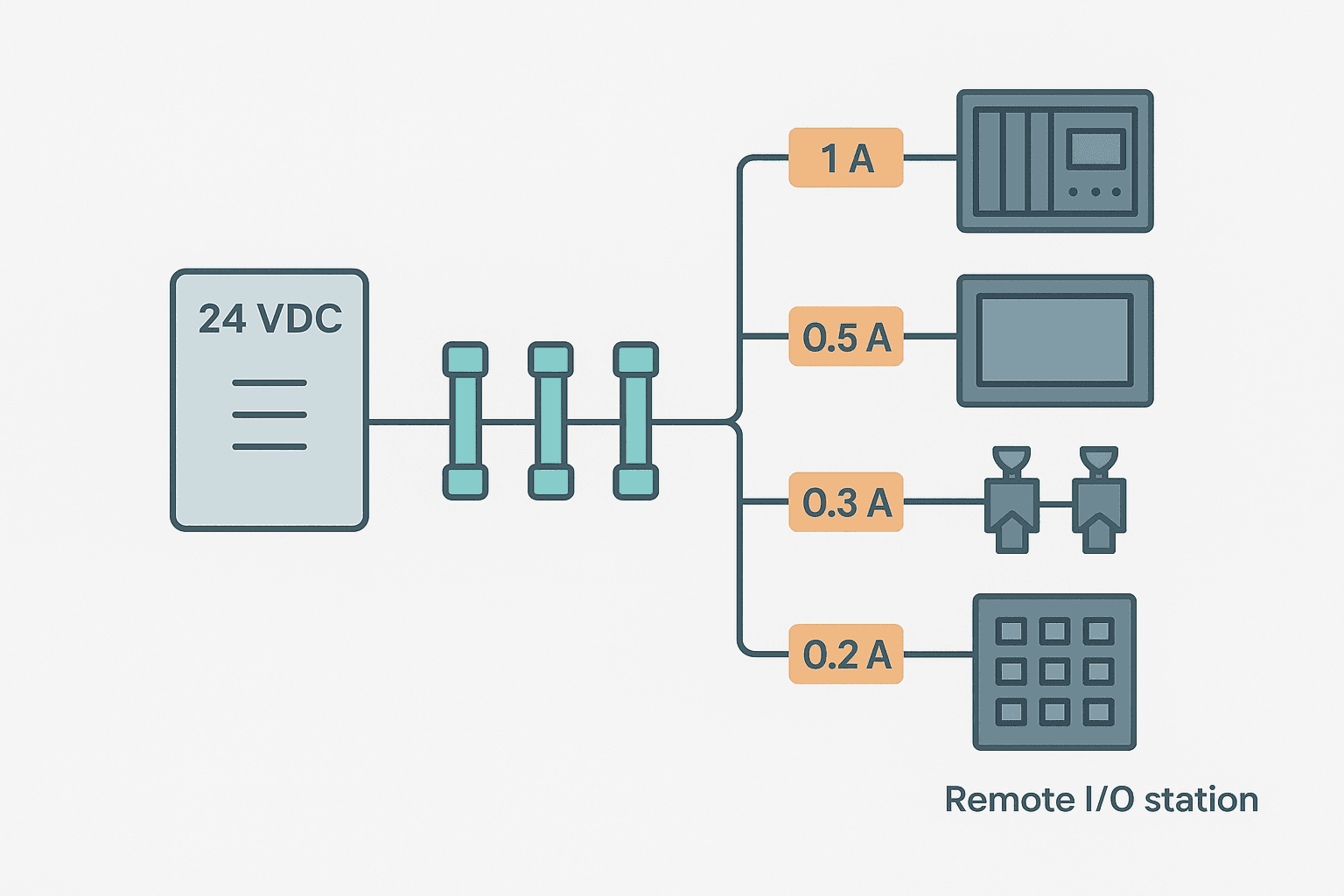
Once you've sized the PSU, you still need to protect the individual branch circuits. A 20 A PSU feeding 12 circuits should not have a single 20 A fuse protecting the whole bar. If one branch shorts, the PSU delivers 20 A into the fault, and everything connected to the common bar sees the voltage sag while the PSU's internal protection fights the fault.
Use individual fuses or miniature circuit breakers per branch. Size each branch fuse to the conductor ampacity and to the actual load, not to the PSU rating. A solenoid valve circuit on 0.75 mm2 wire with 4 A load gets a 6 A fuse, not a 20 A one. Phoenix Contact and Weidmuller both make compact 24 VDC fuse terminal blocks that fit neatly on the distribution bar. For a deeper look at fuse and breaker selection logic, see Fuse vs Breaker Selection for Control Panels.
Cable Sizing for the 24 VDC Feed
The conductor from the PSU to the distribution bus needs to handle the full PSU output current without excessive voltage drop. A 20 A PSU feeding a bus 1.5 m away over 1.5 mm2 copper wire drops about 0.4 V at full load. That's 1.7% of 24 V, which is acceptable. Double the run length or halve the wire size and you're at 3.4%, which starts to matter for devices with a minimum operating voltage of 18 or 20 VDC.
Keep the PSU-to-bus run as short as physically possible. Use 2.5 mm2 or 4 mm2 for the main feed on any PSU above 10 A. For the individual branch circuits within the panel, 0.75 mm2 or 1.0 mm2 is standard for most I/O and valve loads. You can use the wire and cable sizing calculator to check ampacity and voltage drop for your specific run lengths and conductor sizes.
A Quick Sizing Checklist
- Build a complete load list from actual spec sheets, not estimates
- Sum continuous load current (holding current for all devices)
- Check inrush for simultaneous energisation scenarios
- Find the worst-case panel internal temperature and apply the PSU derating curve
- Add 25% margin to the derated load figure
- Select the next standard PSU size above that figure
- Consider splitting into logic and field device circuits
- Specify PSU diagnostic output wired to a PLC input
- Fuse every distribution branch individually
- Size conductors for ampacity and voltage drop
It takes maybe 30 minutes to do this properly for a typical panel. That's a much better use of time than a field service trip to swap a PSU that tripped under load three months after delivery.
Frequently asked questions
How do I calculate the size of a 24 VDC power supply for a PLC panel?
What size cable should I use for a 24 VDC power supply output?
Can I run PLC logic and solenoid valves on the same 24 VDC supply?
What does 24 VDC power supply derating mean and why does it matter?
Do I need redundant 24 VDC power supplies?
How do I protect individual 24 VDC branch circuits in a control panel?
Learn this by building it
There is a PLC in this site. It runs a real scan engine, checks your logic against the same tests a working machine would fail, and needs no download and no account.
Open the exercisesFree, no signup, runs in your browser. See all 16 exercises.
Was this helpful?