3-Wire Sensor Wiring: PNP vs NPN to PLC Inputs
You have a proximity sensor on the bench, three wires staring at you, brown, blue, and black, and a PLC input card that may be sinking or sourcing. Wire it wrong and the input either never turns on, stays permanently on, or you blow the output transistor inside the sensor. This happens constantly in the field, and it costs time every single time.
This post gives you the wiring rules you need, explains why they work, and covers the gotchas that get people every few months even after years on the job.
The three wires and what they do
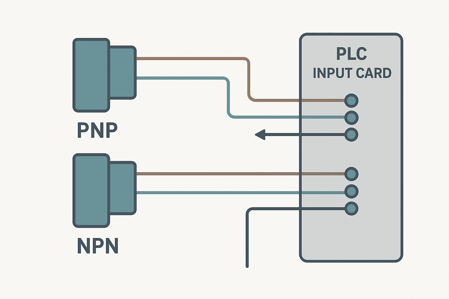
Every standard 3-wire DC sensor follows IEC 60947-5-2 color coding. Brown is the supply positive (typically 24 VDC). Blue is the supply negative (0 V / common). Black is the signal output. Some sensors add a fourth white wire for a complementary output, but ignore that for now.
| Wire color | Function | Connect to |
|---|---|---|
| Brown | 24 VDC supply + | 24 V rail |
| Blue | 0 V supply common | 0 V / DC common rail |
| Black | Signal output | PLC input terminal |
| White (if present) | Complementary output | Second PLC input or leave open |
PNP vs NPN: what the sensor actually does on the black wire
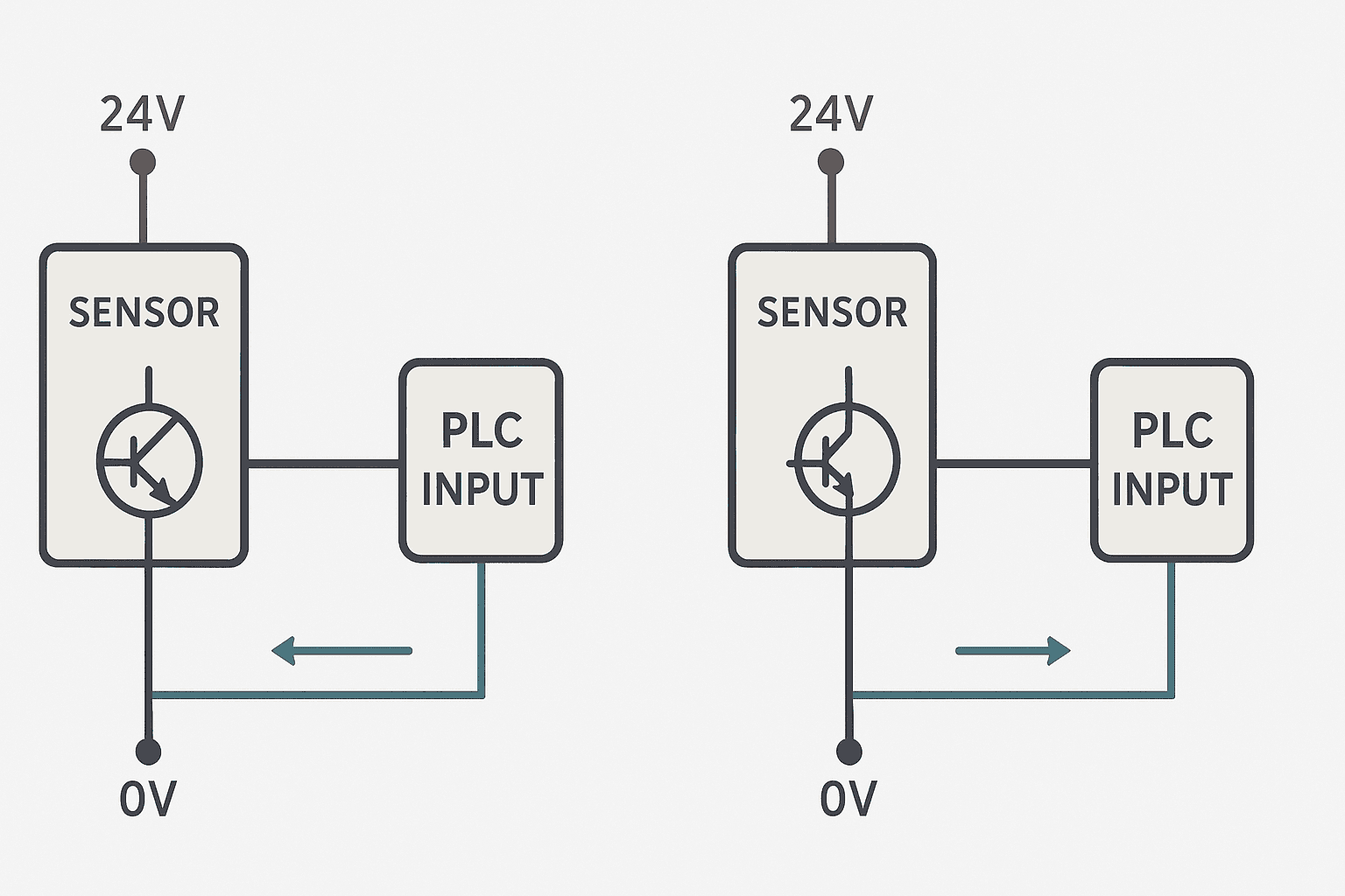
The difference between PNP and NPN is about which direction the signal current flows through the black wire when the sensor detects a target.
PNP (sourcing sensor): When active, the internal transistor connects the black wire to the positive supply. Current flows out of the black wire toward the PLC input. The PLC input sees a high voltage, roughly 24 V, to turn on. PNP sensors are sometimes called sourcing sensors because they source current to the load.
NPN (sinking sensor): When active, the internal transistor connects the black wire to the negative supply (0 V). Current flows into the black wire, away from the PLC input and toward the sensor. The PLC input is pulled down toward 0 V. NPN sensors are called sinking sensors because they sink current from the load.
Sinking vs sourcing PLC inputs: the other half of the equation
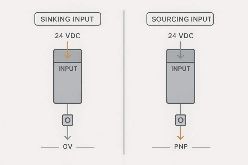
The sensor type alone does not determine how you wire things. The PLC input card has its own topology, and you need to match sensor and input correctly. If you want the full background on sinking and sourcing I/O card types, the post on sinking vs sourcing PLC I/O covers that in depth. Here is the quick version as it applies to sensor wiring.
Sinking input card (NPN input card, Type 1 or Type 3): The input terminal sinks current. It provides a path to 0 V internally. To turn it on, you need to supply current into the input terminal from an external 24 V source. This means it wants a PNP (sourcing) sensor on the black wire.
Sourcing input card (PNP input card, Type 2): The input terminal sources current. It internally connects to 24 V. To turn it on, you need to pull the input terminal down toward 0 V. This means it wants an NPN (sinking) sensor on the black wire.
The complete wiring matrix
| Sensor type | PLC input card type | Does it work? | Common in |
|---|---|---|---|
| PNP (sourcing) | Sinking (NPN) input | Yes, correct match | Europe, most modern Siemens and Beckhoff setups |
| NPN (sinking) | Sourcing (PNP) input | Yes, correct match | Japan (Mitsubishi, Keyence, Omron default), older US installs |
| PNP (sourcing) | Sourcing (PNP) input | No, both push to 24 V, input does not switch | Common wiring mistake |
| NPN (sinking) | Sinking (NPN) input | No, both pull to 0 V, input does not switch | Common wiring mistake |
Step-by-step wiring for a PNP sensor to a sinking input
This is the most common combination in European and modern North American installations. The sensor is PNP, the Siemens ET 200SP, Rockwell 1734-IB8, or Beckhoff EL1008 input card is sinking.
- Connect the sensor's brown wire to the 24 VDC supply rail.
- Connect the sensor's blue wire to the 0 V (DC common) rail.
- Connect the sensor's black wire to the PLC input terminal (e.g., I0.0 on an S7-1200).
- The input card's COM terminal connects to 0 V. On a sinking card this is the internal reference, not an isolated common.
- When the sensor detects a target, the black wire goes to ~24 V, current flows through the input impedance (typically 2.4 kΩ to 5.6 kΩ) and returns via the COM to 0 V. The input turns on.
Step-by-step wiring for an NPN sensor to a sourcing input
This is the standard in Japan and still common in Keyence, Omron, and Mitsubishi installations. The sensor is NPN, the Mitsubishi QX40 or Omron CJ1W-ID231 input card is sourcing.
- Connect the sensor's brown wire to the 24 VDC supply rail.
- Connect the sensor's blue wire to the 0 V rail.
- Connect the sensor's black wire to the PLC input terminal.
- The input card's COM terminal connects to 24 V. On a sourcing card, this is the internal supply reference.
- When the sensor detects a target, the black wire is pulled to ~0 V. Current flows from the COM (24 V) through the input impedance, through the black wire, and into the sensor's NPN transistor to 0 V. The input turns on.
What about bipolar and auto-sensing inputs?
Some modern input cards, particularly from Beckhoff (EL1012) and Phoenix Contact (ILC 1x1 range), accept both PNP and NPN sensors on the same terminal. They do this by sensing the polarity of the current and switching the internal reference accordingly. If you have one of these, life is simpler. But you still need to wire the blue wire to 0 V and the brown wire to 24 V correctly. The card handles the black wire either way.
Do not assume your card is bipolar. Read the datasheet. Most cards sold as 'Type 1/3' are sinking only.
Gotchas that will catch you in the field
Sensor LED on, PLC input off
This is the classic symptom of a type mismatch. The sensor is working fine (its internal LED fires), but the PLC sees nothing. Nine times out of ten you have a PNP sensor on a sourcing input, or an NPN sensor on a sinking input. Both sides are trying to do the same job and no current flows. Swap the sensor type or swap the card.
Input stuck ON even with no target
This usually means the COM terminal is wired to the wrong polarity. For a sinking card, if you accidentally connect COM to 24 V instead of 0 V, the input sees voltage at both ends and latches on. Check your COM wiring first before suspecting the sensor.
The sensor heats up and fails
A PNP sensor wired to a sourcing input creates a near short-circuit path when the sensor fires. The sensor's output transistor tries to drive 24 V into a terminal that is already internally connected to 24 V. Current is limited only by the very low on-resistance of the transistor plus wire resistance, which can hit 200 mA or more. The transistor overheats and fails within minutes. This is the most damaging wiring mistake you can make.
Long cable runs and input noise
Beyond about 30 m of unshielded cable, you can get false triggering on inputs due to capacitive coupling from adjacent AC cables. Use shielded cable, ground the shield at one end only (the panel end), and keep sensor cables away from VFD output cables. A 10 nF filter capacitor across the input terminal to COM can help with high-frequency noise, but check your input's minimum pulse width spec first. A 10 ms hardware filter eliminates the noise but also limits you to detecting targets that dwell for at least 10 ms.
Two-wire sensors: the leakage current problem
Two-wire sensors (no separate blue supply wire) work differently. They always pass a small leakage current, typically 1 mA to 2 mA, even when off. Some PLC inputs with low threshold voltages or high input impedance will see this leakage as an ON state. If you have a two-wire sensor that reads permanently ON, add a bleed resistor of about 8.2 kΩ across the input terminal to COM. This pulls the leakage current away before it reaches the input threshold. The resistor value matters: too low and you reduce the ON voltage below the threshold; too high and it does not bleed enough.
Identifying sensor type when you have no datasheet
Power the sensor from 24 VDC (brown to +, blue to 0 V). Put a multimeter in DC voltage mode. Probe the black wire to the 0 V rail. Trigger the sensor by moving a metal target close.
- If the black wire goes to ~24 V when triggered: PNP (sourcing sensor). Wire to a sinking input.
- If the black wire goes to ~0 V when triggered: NPN (sinking sensor). Wire to a sourcing input.
- If the black wire stays near 12 V regardless: you have a 2-wire AC sensor or a wiring fault.
Regional defaults you need to know
If you commission equipment from different parts of the world, you will run into sensor type mismatches constantly unless you understand the regional conventions.
| Region | Default sensor type | Default PLC input type | Key brands |
|---|---|---|---|
| Europe | PNP (sourcing) | Sinking (NPN) | Siemens, Beckhoff, Phoenix Contact, Sick, Pepperl+Fuchs |
| Japan | NPN (sinking) | Sourcing (PNP) | Keyence, Omron, Mitsubishi, Panasonic, Turck JP |
| North America | PNP (sourcing) modern, mixed legacy | Sinking (NPN) modern, mixed legacy | Rockwell, Banner, Turck US, Balluff |
| China OEM | Often NPN, check label | Mixed, often sourcing | Autonics, Fotek, various |
When a Japanese machine arrives at a European plant and the integrator starts adding Siemens I/O, the NPN sensors from the machine meet sinking Siemens inputs. Nothing works. The fix is either to replace sensors with PNP versions, add a sourcing input card, or use a small relay or transistor adapter circuit to invert the signal. The relay approach adds latency and cost; replacing sensors is cleaner if you have access.
PLC input filter and response time specs to check
Not all inputs are equally fast. A standard DI module on an S7-1200 has a default input filter of 6.4 ms. If your inductive prox is detecting a gear tooth on a shaft spinning at 500 RPM with 60 teeth, the pulse period is 2 ms, well below the filter window. You will miss pulses entirely. For high-speed counting you need a fast input channel (HSC, high-speed counter input) with a filter of 0.05 ms or less. Check your module specs before assuming any input will catch fast events.
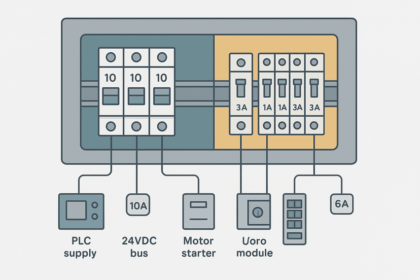
For panel design details on fusing the 24 VDC sensor supply rail, see the post on fuse and breaker selection for control panels. Sensor circuits typically need a 0.5 A to 2 A fast-blow fuse per group of 8 to 16 sensors, not a shared 10 A breaker across the whole 24 V rail.
Get the sensor type, input card type, and current direction right and 3-wire sensors are bulletproof. Get any one of them wrong and you are chasing phantom faults for hours. Print the wiring matrix from this post, tape it inside your panel door, and the matching problem disappears.
Frequently asked questions
Can I use a PNP sensor with a sourcing PLC input?
How do I tell if my PLC input card is sinking or sourcing?
What is the difference between a 2-wire and 3-wire sensor?
My sensor LED turns on but the PLC input stays off. What should I check?
Can one sensor wire to two different PLC inputs?
Why do Japanese machines mostly use NPN sensors?
Learn this by building it
There is a PLC in this site. It runs a real scan engine, checks your logic against the same tests a working machine would fail, and needs no download and no account.
Open the exercisesFree, no signup, runs in your browser. See all 16 exercises.
Was this helpful?