4-20 mA Scaling in a PLC: ST and Ladder Code
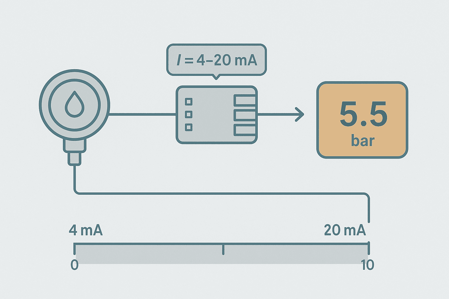
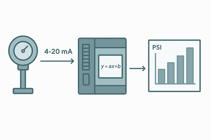
You wire up a pressure transmitter, the analog input card reads 13,926, and now you need to show the operator 5.5 bar. That conversion, raw integer count to real engineering units, is 4-20 mA scaling. It trips up a surprising number of engineers because there are actually three variables to get right: the signal range, the card's count range, and the instrument's span. Get any one wrong and your display is off, sometimes dangerously so.
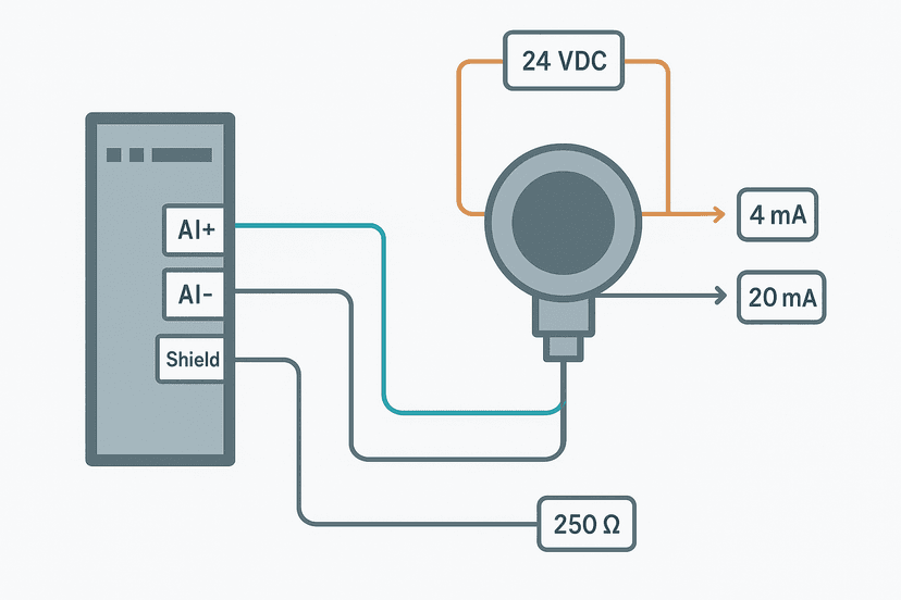
This post covers the full picture: the formula, the gotchas around 4 mA live-zero offset, clipping for out-of-range inputs, and actual runnable code for both Studio 5000 structured text and TIA Portal (S7-1200). If you haven't sorted the wiring side yet, PLC Analog Input Wiring: 4-20 mA Step by Step covers that first. And if you want to cross-check your numbers fast, the analog scaling calculator on this site handles the arithmetic for you.
4-20 mA Scaling: The Core Formula
The linear scaling formula is always the same regardless of platform:
EU = EU_Lo + (EU_Hi - EU_Lo) * (Raw - Raw_Lo) / (Raw_Hi - Raw_Lo)
Where EU is the engineering-unit result, EU_Lo and EU_Hi are the instrument's span endpoints, Raw is the live count from the module, and Raw_Lo / Raw_Hi are the counts that correspond to 4 mA and 20 mA respectively. Nothing fancy, just a linear interpolation.
Why 4 mA, Not 0 mA?
The 4 mA live-zero exists so you can distinguish a dead loop (0 mA, broken wire) from a genuine zero-signal reading. A transmitter at 4 mA is saying "I'm alive and the process value is at the bottom of my range." This is why you never set Raw_Lo to 0 counts unless your module is explicitly configured for a 0-20 mA mode. Most field instruments are 4-20 mA, so your Raw_Lo must correspond to 4 mA, not 0 mA.
Count Ranges by Platform and Module
This is where most scaling errors happen. Different modules use different integer ranges even for the same 4-20 mA signal. Check your module manual, but the common ones are below.
| Platform / Module | 4 mA count (Raw_Lo) | 20 mA count (Raw_Hi) | Notes |
|---|---|---|---|
| Rockwell 1769-IF4 (0-20 mA mode) | 3277 | 16383 | 12-bit, use Unipolar Raw/Proportional mode |
| Rockwell 1769-IF4 (0-20 mA, Eng Units mode) | 4.000 | 20.000 | Module scales itself; set EU directly |
| Rockwell 1756-IF16 / 1756-IF8 (default) | 3277 | 16383 | 12-bit, same as 1769-IF4 |
| Siemens S7-1200 AI (default) | 5530 | 27648 | 16-bit signed; 0-27648 = 0-20 mA |
| Siemens S7-1500 AI (high-res mode) | 5530 | 27648 | Same mapping; 27648 = 20 mA |
| CODESYS / generic 12-bit card | 819 | 4095 | 4 mA = 4/20 * 4095 = 819 |
| Generic 16-bit card, 0-65535 | 13107 | 65535 | 4 mA = 4/20 * 65535 = 13107 |
Worked Example: 0-10 bar Pressure Transmitter on a 1769-IF4
Transmitter: 0-10 bar, 4-20 mA output. Module: 1769-IF4, configured for 0-20 mA Unipolar Raw mode. Live raw count: 9853.
- EU_Lo = 0.0 bar, EU_Hi = 10.0 bar
- Raw_Lo = 3277 (4 mA on 0-16383 scale)
- Raw_Hi = 16383 (20 mA)
- Raw = 9853
- EU = 0 + (10 - 0) * (9853 - 3277) / (16383 - 3277)
- EU = 10 * 6576 / 13106 = 10 * 0.5018 = 5.018 bar
So 9853 counts equals roughly 5.0 bar. You can verify this with the analog scaling calculator by plugging in those four boundary values.
Studio 5000 Structured Text: Full Scaling Block
The code below is a reusable inline ST block you can drop into any Logix 5000 routine. It clamps the raw value before scaling so a broken transmitter (0 mA) or over-range signal (>20 mA) doesn't push garbage into your process logic.
// PT101 - Pressure Transmitter, 0-10 bar, 4-20 mA
// Module: 1769-IF4, Raw/Proportional mode, 0-20 mA unipolar
// Raw range: 0-16383 counts

VAR
    PT101_RawCount  : INT  := 0;   // Live count from AI channel
    PT101_RawClamped: INT  := 0;   // After clamp
    PT101_PressBar  : REAL := 0.0; // Scaled engineering unit
    PT101_LowAlarm  : BOOL := FALSE;
    PT101_HighAlarm : BOOL := FALSE;

    Raw_Lo : INT  := 3277;  // 4 mA count
    Raw_Hi : INT  := 16383; // 20 mA count
    EU_Lo  : REAL := 0.0;   // bar at 4 mA
    EU_Hi  : REAL := 10.0;  // bar at 20 mA
    EU_LoAlarm : REAL := 0.5;  // alarm setpoints
    EU_HiAlarm : REAL := 9.5;
END_VAR

// ---- Step 1: Clamp raw input to valid 4-20 mA window ----
IF PT101_RawCount < Raw_Lo THEN
    PT101_RawClamped := Raw_Lo;   // treat broken-wire as 4 mA floor
ELSIF PT101_RawCount > Raw_Hi THEN
    PT101_RawClamped := Raw_Hi;
ELSE
    PT101_RawClamped := PT101_RawCount;
END_IF;

// ---- Step 2: Linear scaling formula ----
PT101_PressBar := EU_Lo
    + (EU_Hi - EU_Lo)
    * INT_TO_REAL(PT101_RawClamped - Raw_Lo)
    / INT_TO_REAL(Raw_Hi - Raw_Lo);

// ---- Step 3: Process alarms ----
PT101_LowAlarm  := (PT101_PressBar < EU_LoAlarm);
PT101_HighAlarm := (PT101_PressBar > EU_HiAlarm);INT_TO_REAL() cast is critical in Logix. If you subtract two INTs and then divide, integer division truncates the result to zero or a wrong whole number. Always cast to REAL before the division, not after.TIA Portal (S7-1200) Structured Text Version
On the S7-1200 the counts are 5530 to 27648 for 4-20 mA. The logic is identical; only the boundary numbers change. Paste this into an FB or OB1 STL/SCL editor.
// PT101 - Pressure Transmitter, 0-10 bar, 4-20 mA
// Module: S7-1200 AI, 4-20 mA mode
// Siemens raw range: 5530 (4 mA) to 27648 (20 mA)

VAR
    PT101_RawCount  : INT  := 0;
    PT101_RawClamped: INT  := 0;
    PT101_PressBar  : REAL := 0.0;
    PT101_LowAlarm  : BOOL := FALSE;
    PT101_HighAlarm : BOOL := FALSE;
END_VAR

CONST
    RAW_LO    : INT  := 5530;
    RAW_HI    : INT  := 27648;
    EU_LO     : REAL := 0.0;
    EU_HI     : REAL := 10.0;
    ALARM_LO  : REAL := 0.5;
    ALARM_HI  : REAL := 9.5;
END_CONST

// Clamp to valid signal window
IF PT101_RawCount < RAW_LO THEN
    PT101_RawClamped := RAW_LO;
ELSIF PT101_RawCount > RAW_HI THEN
    PT101_RawClamped := RAW_HI;
ELSE
    PT101_RawClamped := PT101_RawCount;
END_IF;

// Scale to bar
PT101_PressBar := EU_LO
    + (EU_HI - EU_LO)
    * INT_TO_REAL(PT101_RawClamped - RAW_LO)
    / INT_TO_REAL(RAW_HI - RAW_LO);

// Alarms
PT101_LowAlarm  := PT101_PressBar < ALARM_LO;
PT101_HighAlarm := PT101_PressBar > ALARM_HI;
Ladder Logic: CPT Instruction for Scaling in Studio 5000
Some shops still do everything in ladder. In Studio 5000 you can put the whole formula into a CPT (Compute) instruction. The expression field accepts the full linear formula in one line. The rung below fires continuously (unconditional) and writes the result to a REAL tag.
CPT Analog Scaling Rung: 0-10 bar Pressure Transmitter (Studio 5000). Ladder logic: Rung 0: CPT on PT101_PressBar. Unconditional CPT rung that executes every scan. PT101_RawClamped is pre-clamped by a previous rung (see ST code above). EU_Lo=0.0, EU_Hi=10.0, Raw_Lo=3277, Raw_Hi=16383. Result lands in PT101_PressBar (REAL). In Studio 5000, CPT destination must be REAL and the expression must cast INT operands with INT_TO_REAL() before division to avoid integer truncation.
The diagram above evaluates one scan. Run these exact rungs on a real scan cycle to watch the latching and the timers behave.
Run this in the simulatorNegative and Bidirectional Spans
The formula handles negative spans without modification. A temperature transmitter calibrated for -40 to +85 °C just uses EU_Lo = -40.0 and EU_Hi = 85.0. At 4 mA you get -40 °C; at 20 mA you get +85 °C. The math is linear, so the sign takes care of itself.
Inverted spans (where higher current means lower EU value, such as a level transmitter mounted at the bottom of a tank where 20 mA = empty) work the same way: set EU_Lo to the higher value and EU_Hi to the lower. For example, EU_Lo = 100 %, EU_Hi = 0 %. The formula inverts automatically.
Broken-Wire Detection: Going Below 3.8 mA
A healthy 4-20 mA loop sits between 3.8 and 20.5 mA in practice (the IEC 61298-2 standard allows a 5 % over-range, which is roughly 20.8 mA at the top and 3.6 mA at the bottom). If your raw count drops below the 3.6 mA threshold, treat it as a broken wire or failed transmitter, not a valid process value. The clamping code above prevents the alarm setpoints from being tripped by a wiring fault, but you should also set a separate PT101_WireFault bit so operators know the reading is invalid.
// Wire-break detection threshold: 3.6 mA on 1769-IF4
// 3.6 / 20 * 16383 = 2949 counts
CONST
    WIRE_FAULT_THRESHOLD : INT := 2949;
END_CONST

PT101_WireFault := (PT101_RawCount < WIRE_FAULT_THRESHOLD);
Scaling a 3-15 PSI Pneumatic Signal
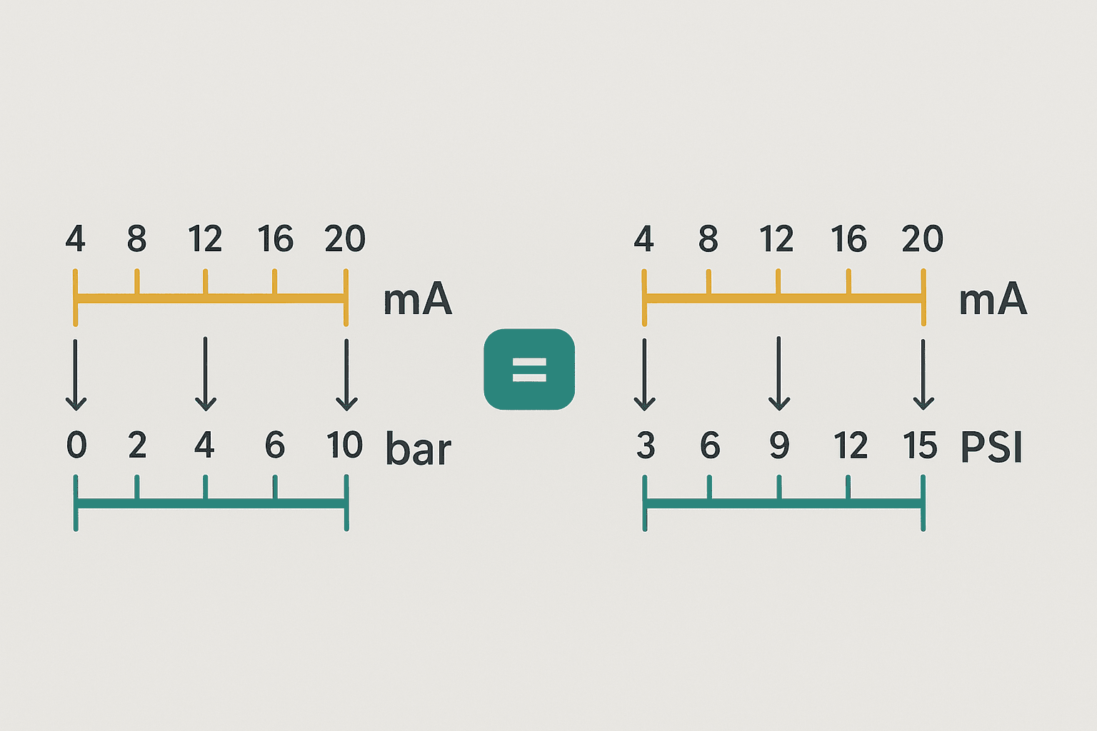
Old pneumatic control loops used 3-15 PSI air signals instead of 4-20 mA. I/P transducers convert between the two. If you have a legacy instrument with a 3-15 PSI span and an I/P that outputs 4-20 mA, the transmitter EU span is simply 3 PSI (at 4 mA) to 15 PSI (at 20 mA). Set EU_Lo = 3.0 and EU_Hi = 15.0 and the formula handles it. Nothing special required.
Making It Reusable: A Function Block Approach
If you have more than two or three analog inputs, hard-coding the constants for each channel is a maintenance problem. A better pattern is a reusable function block (AOI in Logix, FB in TIA Portal) that takes Raw_Lo, Raw_Hi, EU_Lo, EU_Hi, and the raw count as inputs, and returns the scaled REAL plus wire-fault and alarm bits as outputs. You instantiate it once per channel. When a transmitter range changes, you update one tag value instead of hunting through multiple routines.
In Logix, create an Add-On Instruction (AOI) called Analog_Scale_4_20mA. Give it inputs: RawCount (INT), Raw_Lo (INT), Raw_Hi (INT), EU_Lo (REAL), EU_Hi (REAL), Alarm_Lo (REAL), Alarm_Hi (REAL). Outputs: EU_Value (REAL), Wire_Fault (BOOL), Lo_Alarm (BOOL), Hi_Alarm (BOOL). Copy the ST logic from the code block above into the AOI body. Every AI channel then uses one clean tag reference.
Common Scaling Mistakes and How to Avoid Them
- Using 0 counts as Raw_Lo on a 4-20 mA channel. The live-zero is at 4 mA, not 0 mA. Your readings will read about 25 % low at mid-scale.
- Integer division before casting to REAL. In Logix and most IEC platforms, INT/INT = INT (truncated). Always cast first.
- Forgetting to match the module's configured mode. A 1769-IF4 in Engineering Units mode already outputs a floating-point mA value; apply the EU formula to that, not to a raw count.
- Not clamping the raw input. Over-range signals (a transmitter pushed past 20 mA by a process excursion) will extrapolate your EU value past the instrument's rated span, which can look like a valid reading but isn't.
- Scaling a 0-10 V module as if it were 4-20 mA. A 0-10 V input has Raw_Lo = 0, not a live-zero offset. Check the module's input type configuration before coding.
- Swapping EU_Lo and EU_Hi when they should be inverted. Double-check by mentally testing: at Raw_Lo, does the formula return EU_Lo? It should.
The 4-20 mA Scaling Formula: The PLC Engineer's Guide post on this site covers the pure mathematics side in more depth if you want to go further into span, zero and suppressed-zero calibration.
Frequently asked questions
What raw count does 4 mA correspond to on a Siemens S7-1200 analog input?
How do I scale 4-20 mA to engineering units in Studio 5000 structured text?
How do I detect a broken 4-20 mA wire in PLC logic?
Can I use the same scaling formula for a 3-15 PSI pneumatic transmitter converted to 4-20 mA?
What is the NORM_X and SCALE_X approach in TIA Portal and when should I use it?
Why do I get a zero or wrong result when scaling in ladder logic with a CPT instruction?
Now build it
You have just read about CPT. Reading a rung and making one behave are different skills, and the second one is the job.
Cycle Warning Window (compare)
Advancedabout 15 minA 3-second cycle should flash a warning during its FINAL second only. You can't do that with DN bits alone: you compare the timer's accumulated value against a number.
Build this rungFree, no signup, runs in your browser. See all 16 exercises.
Was this helpful?