Intermittent Sensor Faults: How to Find Them
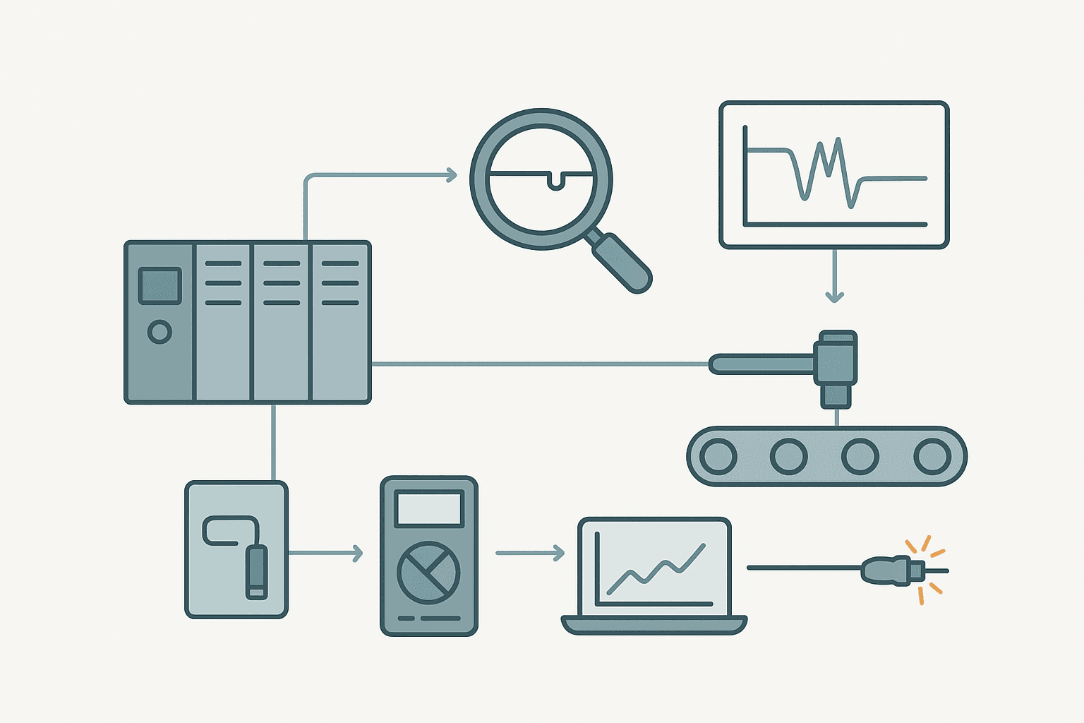
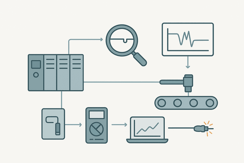
The fault that clears itself before you get to the machine is the one that costs the most. An intermittent sensor fault can cause random machine stops, phantom alarms and rejected product for weeks before anyone isolates the root cause. And every time maintenance arrives, the signal is rock solid. This post covers how to systematically hunt down and permanently fix intermittent sensor faults in PLC-controlled machinery.
Why Intermittent Sensor Faults Are Different
A hard fault is actually easy. The input stays off, you swap the sensor, done. An intermittent fault only appears under a specific combination of conditions: machine vibration at full speed, cable flexing through a drag chain, a connector that is slightly loose, or a supply rail that sags when three outputs turn on simultaneously. Remove any one of those conditions and the fault hides completely.
The most common physical root causes, in rough order of how often I see them in the field, are: cable damage inside a drag chain, an intermittent crimp or ferrule at a terminal block, a loose M8/M12 connector body, vibration-induced contact bounce on a mechanical limit switch, inadequate shielding causing noise-induced false transitions, and a sensor that is thermally marginal and fails only when the cabinet or machine has been running for a couple of hours.
Step 1: Capture the Fault Before You Touch Anything
Your first job is evidence collection, not repair. The worst thing you can do is wiggle the cable, feel the signal come back, and declare it fixed. You have just masked the fault and guaranteed it comes back.
Use your PLC to log the event. In TIA Portal you can set up a data log or use the built-in trace function to record an I/O bit at the scan rate. In Studio 5000, the Logix Designer trend or a simple latch rung with a timestamp tag (using the GSV instruction to read WALLCLOCKTIME) gives you a permanent record of exactly when the bit flickered. In any CODESYS-based system, the logging library or a persistent variable array works well.
Ladder Logic: Capturing an Intermittent Sensor Event
Sensor Dropout Counter and Latch (Studio 5000 / Logix). Ladder logic (3 rungs): Rung 0: examine if Sensor_A_Input is on (XIC), then examine if Sensor_A_FallEdge is on (XIC), then either CTU on Sensor_A_DropCount. Rung 1: examine if Sensor_A_FallEdge is on (XIC), then latch output Sensor_A_DropLatch (OTL). Rung 2: examine if Sensor_A_DropLatch is on (XIC), then examine if HMI_ResetDropLog is on (XIC), then unlatch output Sensor_A_DropLatch (OTU), then either RES on Sensor_A_DropCount. Rung 1: One-shot falling edge detects any dropout on Sensor_A_Input, then the CTU increments Sensor_A_DropCount. Rung 2: Latches Sensor_A_DropLatch on the first dropout so the HMI alarm persists even if the signal recovers. Rung 3: Operator reset from HMI clears both the latch and the counter. Tag Sensor_A_DropCount accumulating overnight without any machine alarms is hard evidence of an intermittent fault.
The diagram above evaluates one scan. Run these exact rungs on a real scan cycle to watch the latching and the timers behave.
Run this in the simulatorStep 2: Correlate the Fault With a Physical Condition
Once you have proof the signal is dropping, you need to know when. Look at the timestamps relative to the machine cycle. Ask yourself:
- Does it only happen when a particular axis is at a certain position? (Cable at maximum extension in the drag chain.)
- Does it happen on every Nth cycle? (Mechanical resonance or a cam that is slightly worn.)
- Does it happen only after 45 to 90 minutes of runtime? (Thermal issue: sensor, cable insulation or a connector with marginal contact resistance.)
- Does it correlate with a large motor or solenoid switching nearby? (Induced noise on an unshielded cable run.)
- Does it happen in a specific ambient condition, like after the extraction fan kicks in and cools the cabinet? (Thermal cycling causing connector movement.)
These correlations narrow the physical location enormously. A fault that only appears when the X-axis is beyond 800 mm of travel is almost certainly a drag-chain cable fault, not a sensor body problem.
Step 3: Isolate the Fault to Cable, Connector or Sensor
Now you can start touching things, methodically. Work from the PLC back toward the field device.
| Location to Test | What to Do | What You Are Looking For |
|---|---|---|
| Terminal block / I/O card input | Measure DC voltage at the input terminal while the machine cycles. Use a meter with a MIN/MAX hold function. | Any dip below the input threshold (typically 15 V DC for a 24 V input) during the fault window. |
| Field connector body (M8/M12) | Wiggle the connector body with the machine stopped and the signal live. Watch the PLC online. | Any flicker in the input bit. A loose connector body is often enough. |
| Cable along the drag chain or conduit | Clamp an alligator clip to the cable shield or outer jacket and flex the run by hand while watching the input. | A flicker during flex confirms cable damage, usually at the entry or exit bend radius. |
| Sensor body | Substitute a known-good sensor on the same cable. Run through the fault conditions. | If the fault disappears, the sensor is the root cause. If it continues, the cable or wiring is at fault. |
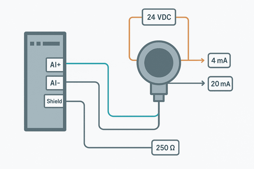
| Power supply rail | Log 24 VDC supply voltage at the sensor's supply terminal during a fault event. | A sag below 20 V DC (the lower end of most 3-wire sensor operating ranges) means supply is marginal. |
The Most Common Physical Culprit: Drag Chain Cable Damage
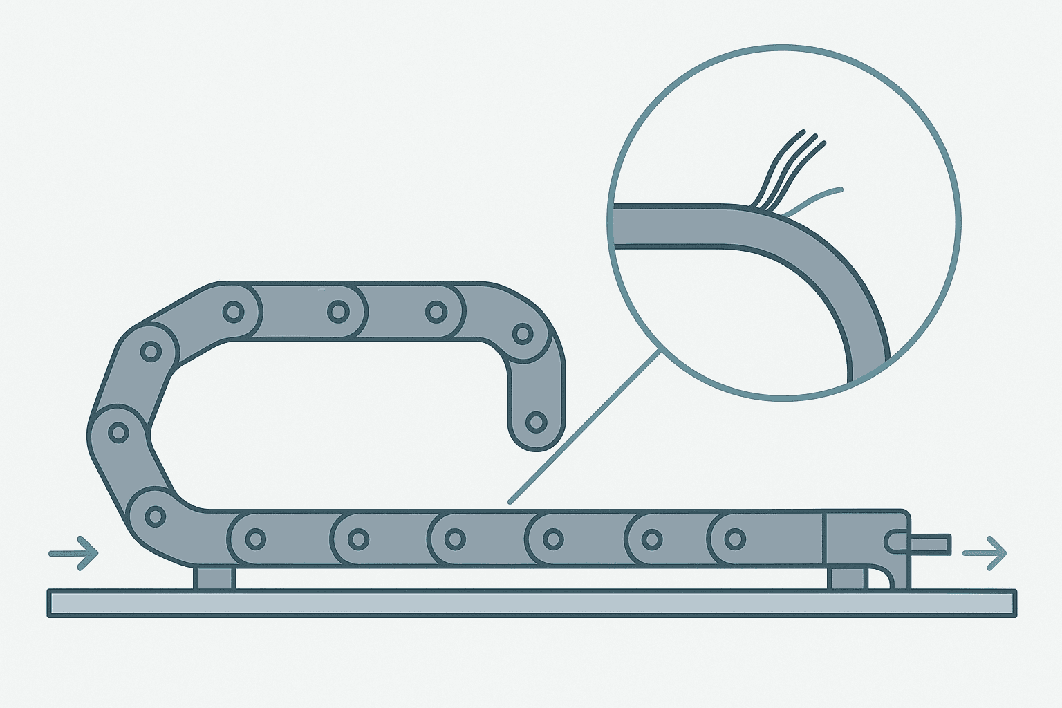
If your machine has a cable carrier (drag chain, energy chain, whatever the brand calls it), cable damage inside the chain is the single most common cause of intermittent sensor faults I have ever seen. The cable looks fine on the outside. The insulation is intact. But internally, one or more conductors have work-hardened and fractured. The break closes under compression and opens under tension, so the fault appears only at one end of the axis travel.
The fix requires using cable rated for continuous flex: look for a specification like 10 million flex cycles, stranded cores with a minimum of 30 wires per conductor, and a PUR outer jacket rather than PVC. Igus chainflex and Lapp Ölflex are the two catalogues I reach for most often. Routing matters too: the cable must be secured at both ends of the chain with the correct bend radius for the chain pitch. A cable flopping loose inside the chain will fail in months regardless of its specification.
Noise-Induced False Transitions
Not every intermittent fault is a wiring break. If your dropout counter spikes every time a large contactor or VFD fires, you are looking at induced noise rather than a physical break. The fix is different: you need to address the cable routing and shielding.
- Separate sensor cables from power cables by at least 100 mm. Cross them at 90 degrees if they must intersect.
- Use shielded cable for sensors in noisy environments and terminate the shield at one end only (the panel end, grounded to the cabinet earth bar, not to the sensor body).
- Check that the 24 VDC common (0 V) is solidly grounded at the panel. A floating common is an antenna. See the Control Panel Grounding post for the correct earthing topology.
- Add an input filter in the PLC if the hardware supports it. Most Siemens ET200 modules let you set digital input filter time from 0.1 ms to 20 ms. A 3 ms filter will kill a noise spike without affecting any real sensor signal on a machine running at normal speed.
Sensor-Side Causes Worth Checking
The sensor body itself is sometimes the problem, but it is usually the last thing I suspect because sensors are solid-state and fairly reliable. When they do fail intermittently, the most common mechanisms are:
- Thermal drift: An inductive proximity sensor with marginal switching distance will work fine cold but drop out when it heats up and the oscillator frequency shifts. Measure the switching distance cold and hot. If it changes by more than 10%, the sensor is failing.
- Contamination on the sensing face: Swarf, coolant or paint buildup on an inductive or capacitive sensor face shifts the effective sensing distance. The sensor works until the target moves to the far edge of the sensing range. Clean the face and recheck.
- Vibration-induced mechanical switch bounce: On a mechanical limit switch, worn contacts or a damaged roller arm can produce 5 to 20 ms of contact bounce on each actuation. The PLC scan may catch a false off-state during the bounce window. A solid-state replacement or a software debounce timer (a 20 ms TON before the input is accepted) solves it.
Verifying the Fix
Do not declare victory until the dropout counter you set up in Step 1 has read zero for a full production shift under the worst-case conditions that used to trigger the fault. If it was a thermal fault, that means a full warm-up cycle. If it was a drag-chain fault, that means the full axis travel range at production speed. Reset the counter, run the machine, come back in four hours. Zero dropouts is your acceptance criterion.
Leave the diagnostic rungs in the program with the counter visible on the HMI. The counter costs you nothing in scan time, and the next time someone reports a random fault on that input, maintenance will have immediate, timestamped evidence to work from instead of starting from scratch.
Quick Reference: Fault Type vs Most Likely Cause
| Symptom Pattern | Most Likely Cause | First Action |
|---|---|---|
| Fault only at one end of axis travel | Drag chain cable fracture at bend entry | Flex cable by hand at chain exit, watch PLC input bit |
| Fault only after 45+ min runtime | Thermal: sensor, connector or marginal supply | Log supply voltage and sensor output during warm fault window |
| Fault correlates with large motor/contactor switching | Induced noise on unshielded cable | Check cable routing and shield termination |
| Fault on every Nth cycle with consistent timing | Mechanical switch bounce or worn cam/target | Oscilloscope on input terminal, measure bounce duration |
| Fault appears when cabinet door is opened or closed | Loose terminal ferrule vibrated by door | Re-torque all terminals on that circuit, check ferrule crimp quality |
| Fault appears random, no correlation | Loose M8/M12 connector body | Wiggle each field connector with machine live, replace any that flicker |
Frequently asked questions
How do I catch an intermittent sensor fault that clears itself before I arrive?
What is the most common cause of intermittent sensor faults on linear-axis machines?
Can a PLC input filter fix an intermittent sensor fault?
How do I tell the difference between a wiring fault and a failing sensor?
Why does my sensor fault only appear after the machine has been running for an hour?
Should I leave diagnostic counter rungs in the production program?
Now build it
You have just read about TON. Reading a rung and making one behave are different skills, and the second one is the job.
Flasher
Intermediateabout 15 minTwo timers chained in a loop make a lamp blink: the classic two-TON flasher used for warning beacons everywhere. Your first taste of timers driving each other.
Build this rungFree, no signup, runs in your browser. See all 16 exercises.
Was this helpful?