Control Panel Wire Routing and Segregation
Bad wire routing is one of the most common causes of noise problems in PLC panels, and it is almost always baked in at build time. By the time you are chasing a spurious analog reading or an intermittent fieldbus dropout, the wires are already dressed and tied. Getting the routing right upfront costs nothing extra. Getting it wrong costs days of troubleshooting.
Why control panel wire routing matters
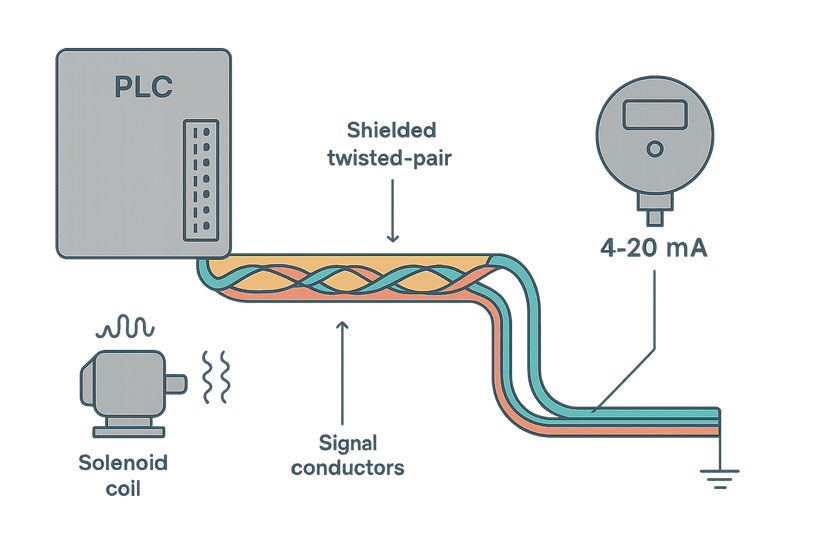
Every current-carrying conductor generates a magnetic field. Every voltage change generates an electric field. When you bundle a 480 VAC motor feed next to a 4-20 mA thermocouple lead, you are creating a transformer and a capacitor at the same time. The induced noise can easily swing 1-2 mA on a 20 mA span, which is 5-10% error before you have even looked at grounding. On a PLC digital input, it might not matter. On a precision flow measurement feeding a PID loop, it absolutely does.
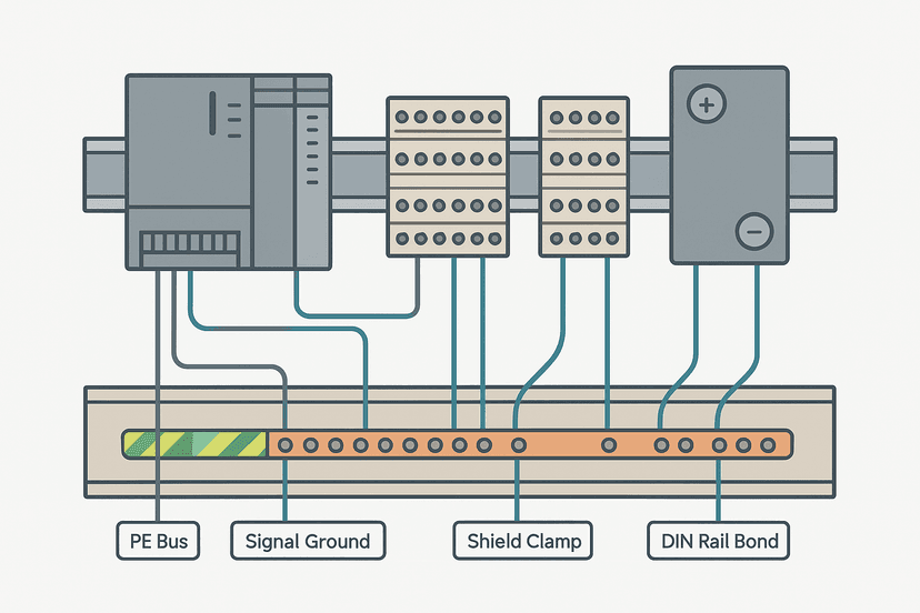
The interference mechanisms are capacitive coupling (voltage fields), inductive coupling (magnetic fields) and common-impedance coupling (shared return paths). Wire routing and segregation address the first two directly. Good grounding handles the third. See the post on Control Panel Grounding: The Right Way to Do It for that side of the story.
The three-zone segregation model
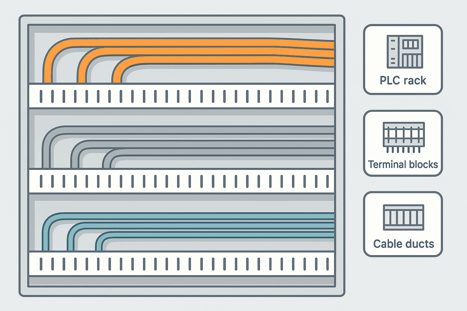
The simplest and most field-proven approach is to divide your enclosure into three wiring zones and never mix them inside a common duct run.
| Zone | Wire types | Typical voltage | Duct colour (IEC 61439 convention) |
|---|---|---|---|
| Zone 1: Power | Mains feeds, transformer primaries/secondaries, VFD output to motor, large contactors | 120/230/480 VAC or high-current 24 VDC bus | Grey or black |
| Zone 2: Control | 24 VDC I/O wiring, coil circuits, PLC I/O modules, relay outputs, pilot lights | 24 VDC (typical) | Blue |
| Zone 3: Signal / Instrumentation | 4-20 mA loops, thermocouple leads, encoder cables, fieldbus (PROFIBUS, EtherNet/IP), serial comms | 0-10 V, mV-level, 5-24 VDC | Green or white |
The key rule: Zone 1 wires never share a duct with Zone 3 wires. Zone 2 can share a duct with Zone 3 if you have no choice, but keep a physical separator between them and keep runs short. Zone 1 and Zone 2 can share a duct only for very short distances at 90-degree crossings, never running parallel.
Minimum separation distances
There is no single universal number here, but these figures are widely used in industrial practice and align with IEC 61000-5-2 guidance:
- Power wires (>120 VAC or >10 A) to signal wires: minimum 200 mm (8 inches) parallel separation, or use a grounded metal barrier.
- VFD output leads to any signal wiring: minimum 300 mm (12 inches) and never in the same tray. VFD cables are the worst offenders because of the high dV/dt from PWM switching.
- 24 VDC control wires to analog signal wires: minimum 50 mm (2 inches) if unshielded, or run signal in shielded cable.
- Where a crossing is unavoidable, cross at 90 degrees. A perpendicular crossing minimises the coupled length and therefore the induced voltage.
Practical duct and tray layout inside the enclosure
Most control panels use slotted plastic cable duct (Panduit or equivalent). Here is how to lay out the duct runs to enforce segregation without wasting backplate space:
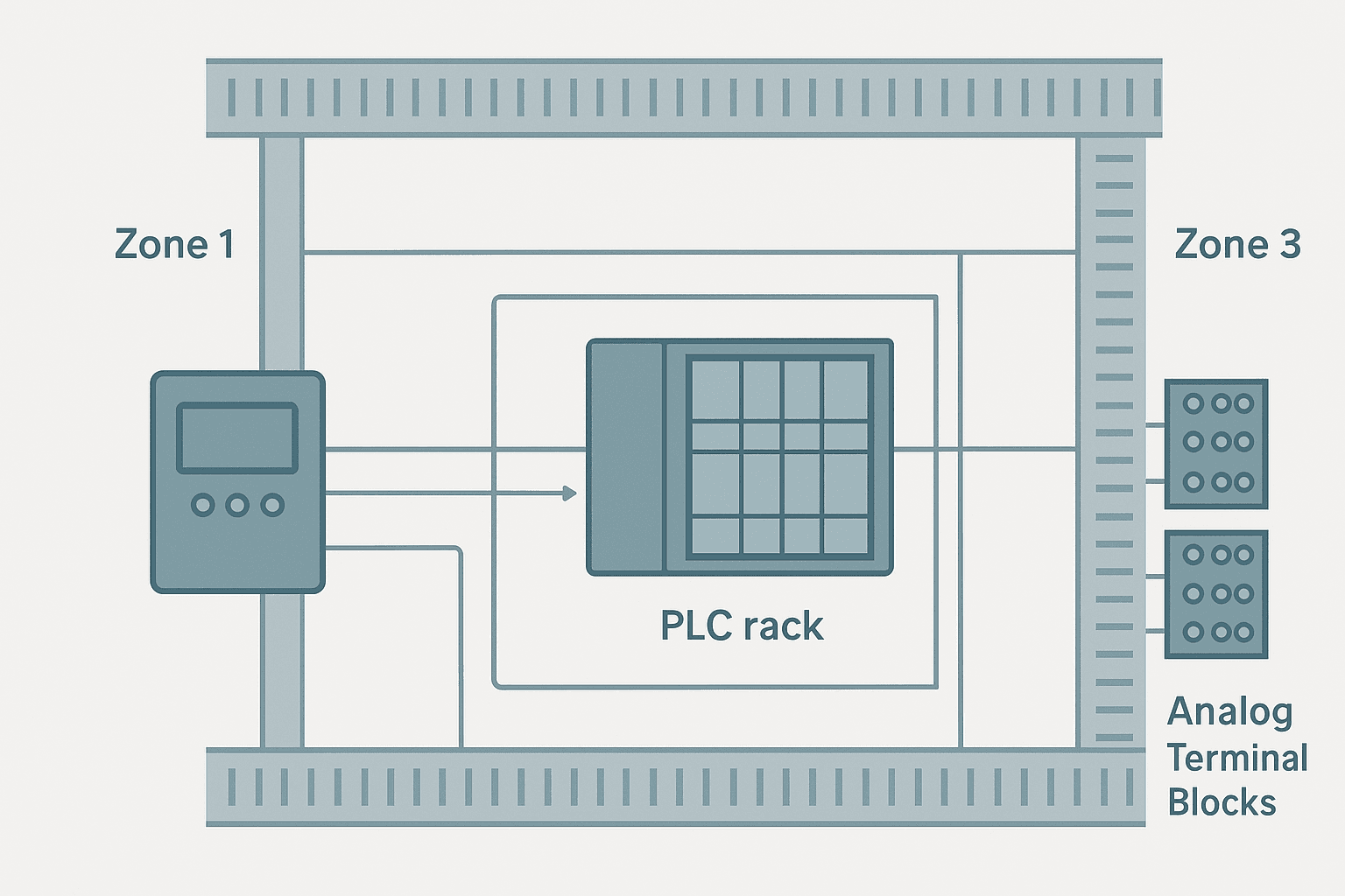
- Run a vertical Zone 1 duct on one side of the backplate (typically the right side if that is where your main terminal blocks land) and a separate vertical Zone 3 duct on the opposite side.
- Zone 2 control wiring can use a central vertical duct, or share the Zone 3 duct with a physical separator strip.
- Horizontal runs connect to the vertical ducts. Keep horizontal Zone 1 runs at the top of the panel and horizontal Zone 3 runs at the bottom, or vice versa, but pick one convention and stick to it across every panel in a project.
- Use separate horizontal ducts for top-of-panel power entries and bottom-of-panel instrumentation entries. Many engineers run conduit knockouts at the top for power and at the bottom for signal, which naturally forces separation.
- Label every duct with the zone it carries. A Dymo or Brady label on each duct end takes 30 seconds and saves hours later.
Crossing wires at 90 degrees: how to actually do it
You will always have at least some crossings. The 90-degree rule is simple in theory and slightly awkward in practice. The trick is to plan your horizontal duct positions so that power horizontals are at a different height from signal horizontals. When a Zone 1 wire needs to reach a component near the Zone 3 duct, it exits the Zone 1 duct, travels horizontally across the backplate (not inside a duct), then enters the Zone 1 duct on the far side. The signal wires in the Zone 3 duct run vertically past that crossing point. The physical crossing happens in open air over a short distance at 90 degrees, not inside a shared duct.
Some panel builders use a grounded aluminium separator strip at crossing points. That is not always necessary for 24 VDC control to signal crossings, but it is worth doing for any crossing involving 480 VAC feeds or VFD cables.
Fieldbus and Ethernet cables inside panels
PROFINET, EtherNet/IP and Modbus TCP cables are twisted-pair with a foil or braid shield. They belong in Zone 3. That said, the RJ-45 connectors on PLCs and switches are often physically close to 24 VDC I/O wiring. Keep the patch cables away from the I/O terminals and route them on their own small duct or along the backplate edge. Ethernet is more immune to noise than 4-20 mA because the differential signalling and transformer isolation at each port reject common-mode noise, but you can still corrupt packets if you route Ethernet cables next to a VFD output for several metres.
PROFIBUS DP uses a characteristic impedance of 150 ohms and is sensitive to cable routing that changes that impedance. Keep PROFIBUS cables away from sharp bends (minimum bend radius is roughly 40 mm for standard Type A cable) and away from high-current conductors. The shield on PROFIBUS cable should be grounded at both ends to the PE rail, which differs from the single-end rule for analog signal cables. If you are not sure about analog cable shielding, the post on Shielding Analog Signal Cables in PLC Panels covers that in detail.
Wire routing from the panel to the field
Segregation does not stop at the enclosure door. The same zone separation should continue in cable trays and conduits from the panel to field devices. Common mistakes:
- Running a thermocouple extension cable in the same conduit as a 240 VAC feed to a heater. The heater is switching at line frequency and the thermocouple is measuring millivolts. This combination will give you a 50/60 Hz noise component on the temperature reading.
- Pulling a PROFIBUS cable through a conduit that already has a VFD motor feed. Reported as 'intermittent comms'. Cause: induced noise from the PWM switching.
- Using the conduit itself as a return path for signal grounds. Always run a dedicated return conductor.
- Coiling excess cable inside the panel. A coil of wire is an inductor and an antenna. Cut cables to length or fold them into flat bundles, not loops.
A few gotchas from real projects
On a food-processing line I worked on, a 4-20 mA flow transmitter was reading 0.3 mA high on every PLC scan. The transmitter was fine, the PLC analog card was fine, the cable shielding was correct. The problem was a 24 VDC solenoid valve cable that had been routed in the same duct as the flow transmitter cable for about 600 mm. Every time the solenoid fired, the inductive kick from the unsnubbed coil capacitively coupled into the analog cable. Adding a snubber diode across the solenoid coil and separating the cables by 150 mm fixed it. Total cost: one 1N4007 diode and 20 minutes of rewiring.
On a machine tool panel, an encoder cable was routed 1.2 metres parallel to a 480 VAC servo drive output cable inside a cable tray. The encoder was reading 2-3 spurious counts per second at rest. Moving the encoder cable to a separate tray on the other side of the machine column eliminated it completely. The servo drive manufacturer's manual actually specified 300 mm minimum separation in the installation notes. Nobody had read it.
Quick reference: control panel wire routing rules
| Rule | Why it matters | Common violation |
|---|---|---|
| Never run Zone 1 power parallel to Zone 3 signal in the same duct | Capacitive and inductive coupling corrupts signal integrity | Stuffing all wires into one large centre duct |
| Minimum 200 mm separation for HV power to signal, 300 mm for VFD output | VFD PWM switching produces high dV/dt noise | VFD cable sharing a tray with encoder or analog cable |
| Cross wires at 90 degrees only, not parallel | Parallel runs maximise coupled length and induced voltage | Running a crossing wire diagonally inside a duct |
| Ground metal cable trays at both ends to PE | Tray acts as a shield if properly grounded | Plastic tray with no grounding at all |
| Snub inductive DC loads (solenoids, relay coils) at the coil | Voltage spikes from unsnubbed coils couple into adjacent signal wires | No snubber on 24 VDC solenoids in the same duct as analog cable |
| Cut cables to length, no coiled excess | Coils act as antennas and inductors | Bundled loops of spare cable zip-tied inside the panel |
Standards that apply
IEC 61000-5-2 gives guidance on earthing and cabling in installations and is the primary reference for EMC-aware wiring practices. IEC 61439 (low-voltage switchgear and controlgear assemblies) does not mandate specific routing distances but requires that the design not compromise safety or function, which implicitly requires segregation. NFPA 79 (Electrical Standard for Industrial Machinery, used in North America) section 13.5 requires that power conductors and signal/communication conductors be separated, though it leaves the distance to the designer. UL 508A references NFPA 79 for industrial control panels.
None of these standards give you a single precise number for every situation, which is why field experience matters. The 200 mm and 300 mm figures above are conservative enough to work in the vast majority of industrial applications. If you are designing a high-sensitivity measurement system (sub-1 mA signal levels, or pulse inputs at >100 kHz), you will want to go further and use grounded metal conduit or shielded cable trays.
Frequently asked questions
Can I run 24 VDC control wiring and 4-20 mA signal wiring in the same cable duct?
How far should VFD output cables be from signal wiring inside a panel?
Does wire segregation replace the need for shielded cable on analog signals?
What is the 90-degree crossing rule and does it really make a difference?
Should cable trays inside a panel be grounded?
Where do Ethernet and PROFINET cables fall in the three-zone model?
Learn this by building it
There is a PLC in this site. It runs a real scan engine, checks your logic against the same tests a working machine would fail, and needs no download and no account.
Open the exercisesFree, no signup, runs in your browser. See all 16 exercises.
Was this helpful?