Shielding Analog Signal Cables in PLC Panels
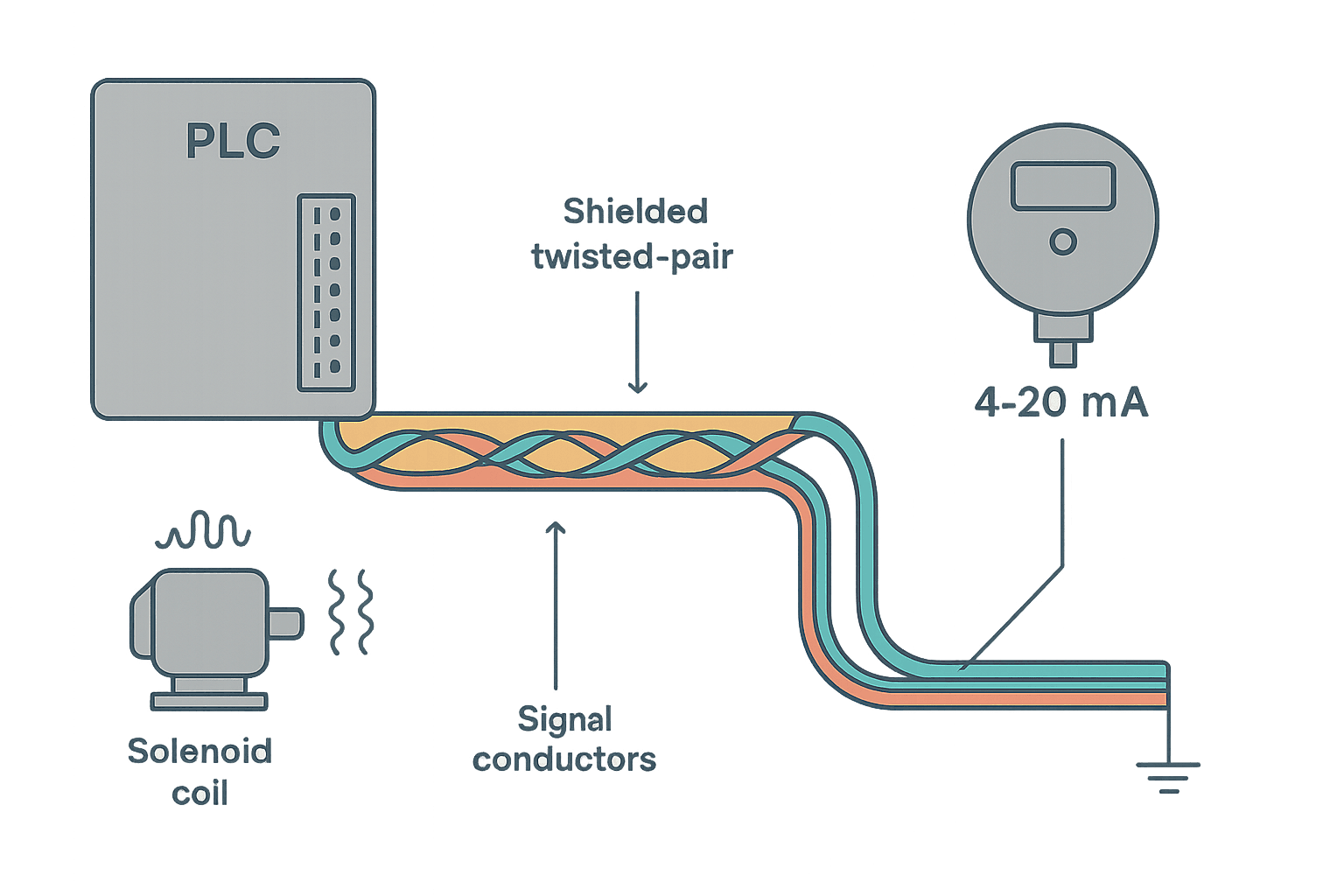
You've wired a pressure transmitter, the field wiring looks clean, and the PLC is reading garbage. The raw count bounces 200 counts every time the VFD ramps up. The transmitter checks out fine on a handheld loop calibrator. So what's wrong? Almost always: the cable shield is either not grounded at all, grounded at the wrong end, or grounded at both ends in a way that turns it into a noise antenna instead of a noise barrier.
Shield grounding is one of those things that feels simple until you've spent a day chasing an intermittent analog fault. This post covers exactly how shields work, the one-end versus both-ends decision, how to terminate them correctly in a terminal strip, and the specific mistakes that bite people in industrial cabinets.
What a Shield Actually Does (and Doesn't Do)
A cable shield is a Faraday cage wrapped around the signal conductors. For electric field (capacitive) coupling, it intercepts induced charge and diverts it to earth, keeping it off the signal wires. For magnetic field (inductive) coupling, the shield does almost nothing. Twisted-pair geometry is what handles magnetic coupling, which is why you should always use shielded twisted pair (STP) for analog runs, not shielded flat cable.
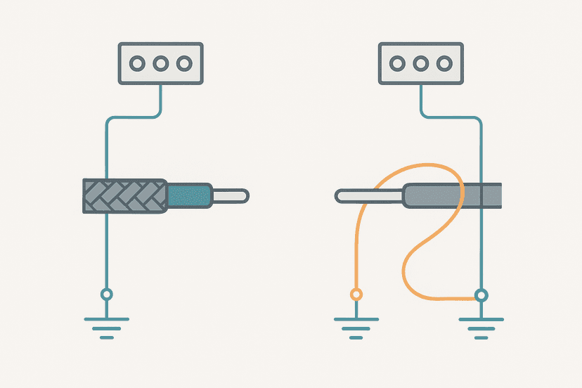
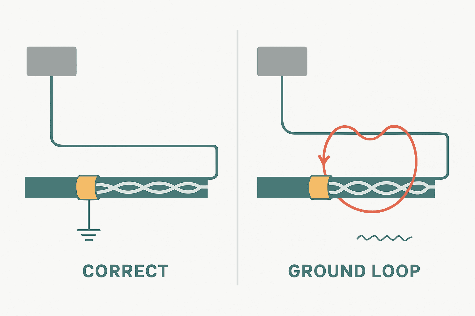
The shield only works when it has a low-impedance path to a stable reference (earth ground). A shield that floats at both ends is just a capacitor, and a capacitor charges up and radiates noise back onto your signal. Ground it at one end, and induced charge drains continuously instead of accumulating.
The Ground Loop Problem: Why Both Ends Is Usually Wrong
If you ground the shield at both ends, you create a closed loop. The two earth ground points in any real plant are rarely at the same potential. There's always some difference, often 0.5 V to 5 V in a noisy environment, sometimes much more near large drives or welding equipment. That potential difference drives a circulating current through the shield. That current generates its own magnetic field, which couples back onto the twisted pair inside. You've built a noise injection circuit.
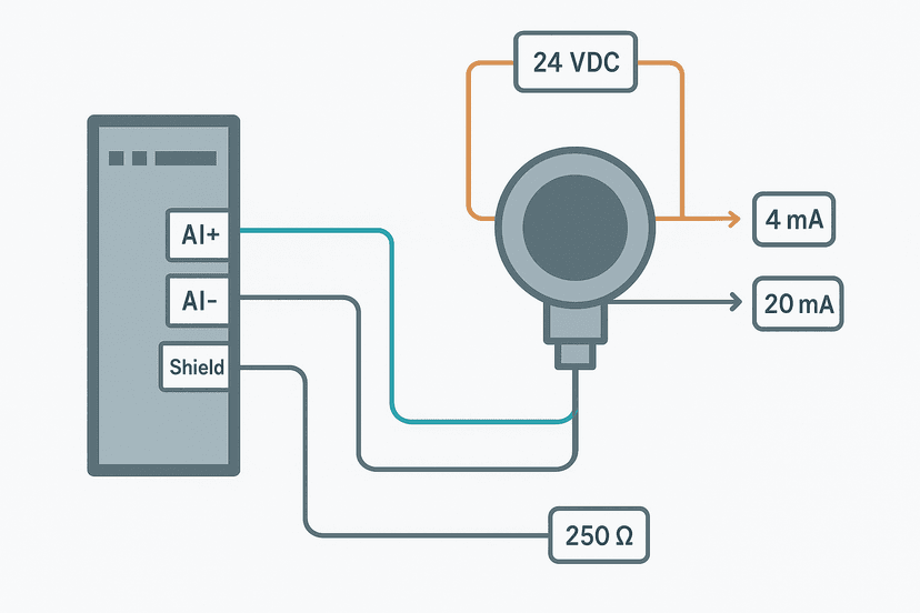
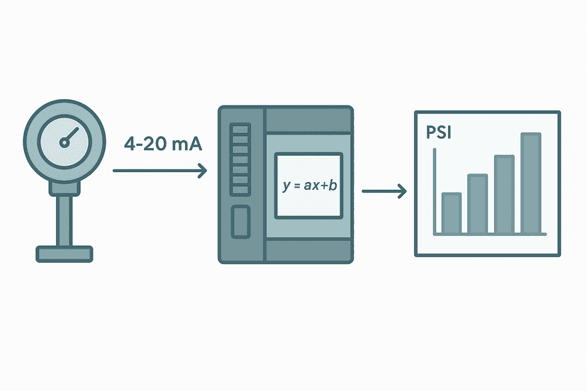
The resulting error on a 4-20 mA loop isn't huge in absolute current terms, but your PLC analog module converts that current to a 16-bit count (or 12-bit on older hardware). A 50 mV noise voltage across a 250 Ω burden resistor produces 0.2 mA of apparent noise, which on a 4-20 mA span maps to 1.25% of full scale. That's 40 counts on a 0-32767 module. Enough to trigger a high-high alarm on a level transmitter if your deadband is set too tight.
When Both Ends Actually Make Sense
There are real cases where you ground both ends. High-frequency signals above roughly 100 kHz (encoder feedback, resolver cables, some fieldbus runs) need a low-impedance shield connection at both ends because at those frequencies, the shield's effectiveness depends on the return path being shorter than a fraction of a wavelength. An encoder running at 1 MHz produces a wavelength of about 300 m in free space, so a 10 m cable is a significant fraction of that, and a floating end reflects noise back.
For Ethernet (100BASE-TX, PROFINET, EtherNet/IP), the cable standard is foil-and-braid shielded, grounded at both ends, with the expectation that the Ethernet physical layer isolates the signal. Cat6A S/FTP to a drive's Ethernet port should be grounded at both the switch and the drive chassis. The transformer isolation inside the Ethernet magnetics handles any ground potential difference.
| Signal Type | Frequency Range | Shield Ground | Notes |
|---|---|---|---|
| 4-20 mA analog | DC to ~100 Hz | Panel end only | Classic instrumentation rule |
| Thermocouple / RTD | DC to ~10 Hz | Panel end only | Same as 4-20 mA |
| 0-10 V analog output | DC to ~1 kHz | Panel end only | Source impedance matters too |
| Incremental encoder | 10 kHz to 1 MHz | Both ends | Use differential receiver |
| Resolver cable | 2-10 kHz carrier | Both ends (per drive vendor) | Follow drive manual exactly |
| PROFIBUS DP | 9.6 kbps to 12 Mbps | Both ends via cable clamp | Belden 3079A or equiv. |
| PROFINET / EtherNet/IP | 100 Mbps | Both ends via chassis clamp | Transformer isolation in PHY |
How to Terminate Shields Correctly at the Terminal Strip
This is where most panels go wrong. The shield drain wire gets landed on a random spare terminal, which is connected to nothing, or worse, to the 24 VDC common because someone confused signal common with earth ground. Here's the correct method:
- Run a dedicated shield bus bar (or a row of terminals jumpered together) connected to the panel's PE (protective earth) rail. This is separate from your 24 VDC common and your signal common.
- At the panel end, strip back the cable jacket about 20-25 mm. Fold the foil/braid back and twist the drain wire. Land the drain wire on the shield bus. Keep this pigtail as short as possible, ideally under 50 mm.
- At the field end, cut the drain wire flush with the jacket and tape it off. It floats. Do not land it on the transmitter housing, a local junction box ground stud, or anything else.
- If the cable passes through a junction box mid-run, bring the drain wire through to both sections and continue the single-end rule: only the panel-end drain wire connects to anything.
- Never share a terminal between signal common and shield earth. They must be separate.
Instrumentation Cable Shielding: The Multiconductor Problem
Multi-pair instrumentation cables (say, a 6-pair or 12-pair cable running multiple 4-20 mA loops in one conduit) have an overall shield plus individual pair shields. The rule gets slightly more nuanced:
- The overall (outer) shield grounds at the panel end only, to the PE shield bus.
- The individual pair shields also ground at the panel end only, each to the same shield bus.
- Do not connect individual pair shields to the overall shield at the field end. You create small local ground loops.
- If individual pair shields are not connected at either end, they're useless. They must be grounded at the panel end to do anything.
Cable Routing: Separation Is Cheaper Than Shielding
A properly grounded shield attenuates electric field interference by 40-60 dB in typical industrial conditions. That sounds like a lot, but a VFD output cable sitting 50 mm away from your analog run can produce field strengths that overwhelm it. The shield is the last line of defence, not the first.
Separate power and signal cables in the panel and in cable trays. The old rule of thumb is 200 mm minimum separation between instrumentation cables and 480 V or VFD output cables. Inside a cabinet, run them in separate trunking on opposite sides if you can. If they have to cross, cross at 90 degrees to minimize the coupled length. These physical habits reduce the noise your shield has to deal with by an order of magnitude before you even think about grounding technique.
Common Shielding Mistakes in Real Panels
- Floating shield at both ends. Looks tidy (drain wire tucked back, taped off everywhere), does absolutely nothing.
- Shield landed on 24 VDC negative. The 0 V rail in many panels is not earth-referenced. Noise couples straight through.
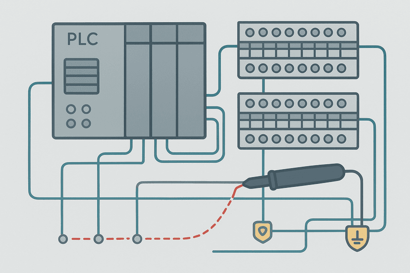
- Shield grounded via a long pigtail through a terminal block that itself is not bonded to PE. The terminal block rail is floating. Check with a multimeter: you should read under 1 Ω from the shield bus to the panel PE stud.
- Grounding the field end at a transmitter housing that is itself floating. Painted enclosures don't count as earth. A transmitter bolted to a painted bracket on a painted beam is floating even if it looks grounded.
- Using the conduit as the shield return. Steel conduit can work in some systems but its impedance is orders of magnitude higher than a dedicated drain wire, and connections at locknuts and couplings corrode over time.
- Mixing shield grounds from different zones on the same bus without checking for potential differences. If your panel serves transmitters in two electrically separate areas of a plant, the shields from each zone should ideally connect to earth at their own end, not share a common bus with the other zone.
Diagnosing a Shielding Problem in the Field
If you suspect a shielding issue rather than a transmitter fault or wiring fault, here's a fast diagnostic sequence:
- Disconnect the field cable at the panel terminal strip and connect a precision 4-20 mA calibrator directly to the analog input terminals. If the PLC reading is now clean and stable, the problem is in the field wiring or the shield arrangement, not the module.
- With the field cable reconnected, use a clamp meter set to AC current around the drain wire (not the signal conductors). If you see more than a few milliamps AC, you have a ground loop or a strong induced current. A floating field end should show essentially zero.
- Measure DC voltage from the shield drain wire to the panel PE rail with a multimeter. It should be under 1 V. More than a few volts means there's a ground potential difference and you need to isolate one end.
- Check noise frequency with an oscilloscope on the analog input (most Siemens S7 and Allen-Bradley modules have a diagnostic raw value accessible in the program). Noise at 50 Hz or 60 Hz suggests a ground loop. Noise at the VFD switching frequency (typically 2-16 kHz) suggests capacitive coupling from poor physical separation.
For a broader look at how to track down ground faults in the panel itself, How to Find a Ground Fault in a Control Panel covers the insulation resistance testing and systematic isolation approach.
Quick Reference: Shielding Rules for Instrumentation Cable
| Rule | Detail |
|---|---|
| Ground at panel end only | For all DC and low-frequency analog signals |
| Shield bus bonded to PE | Under 1 Ω to PE stud, measured with a multimeter |
| Drain wire pigtail length | Keep under 50 mm inside the panel |
| Field end | Cut flush, tape off, do not connect |
| Separation from power cables | 200 mm minimum from VFD output cables |
| Cross-over angle | 90 degrees if signal and power cables must cross |
| Multi-pair cables | Ground each individual pair shield at panel end, separately |
| High-frequency / fieldbus | Follow vendor cable manual, usually both ends via clamp |
Frequently asked questions
Does a cable shield need to be grounded to work?
What happens if you ground a shield at both ends?
Where exactly should the shield drain wire connect in the panel?
Can I use the metal conduit as the shield instead of a drain wire?
Why does my analog signal get noisy only when the VFD is running?
Do thermocouple and RTD cables need the same shield grounding as 4-20 mA cables?
Learn this by building it
There is a PLC in this site. It runs a real scan engine, checks your logic against the same tests a working machine would fail, and needs no download and no account.
Open the exercisesFree, no signup, runs in your browser. See all 16 exercises.
Was this helpful?