Cable Shield Grounding: One End or Both?
Shield termination is one of those things that looks simple until you get a noisy analog signal or a thermocouple reading that drifts with the VFD running nearby. The question of whether to ground a cable shield at one end or both ends has a real, defensible answer. It is not a matter of opinion or habit. It depends on the frequency of the interference, the signal type, and the impedance of your grounding system.
Why Shields Work (and Why Ground Loops Break Them)
A cable shield works by providing a low-impedance path that intercepts electric field interference before it reaches the inner conductors. For this to work, the shield has to be connected to a reference potential, typically earth. The confusion starts when you connect both ends and the two ground points are not at exactly the same potential, which they almost never are in a real plant.
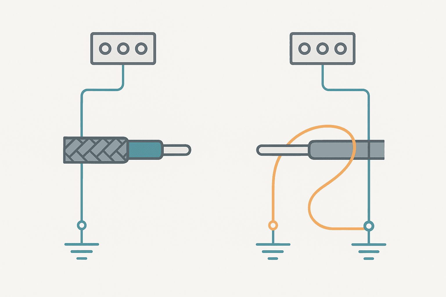
Any voltage difference between the two ground connection points drives a current through the shield. That current creates its own magnetic field, which couples noise directly into the signal conductors running inside the shield. You have turned your shield into an antenna. This is a ground loop, and it is the most common cause of 50 Hz or 60 Hz hum on 4-20 mA loops and thermocouple circuits.
The Single-End Rule for Low-Frequency Analog Signals
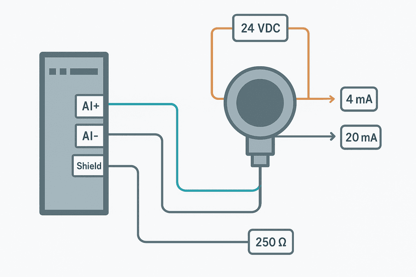
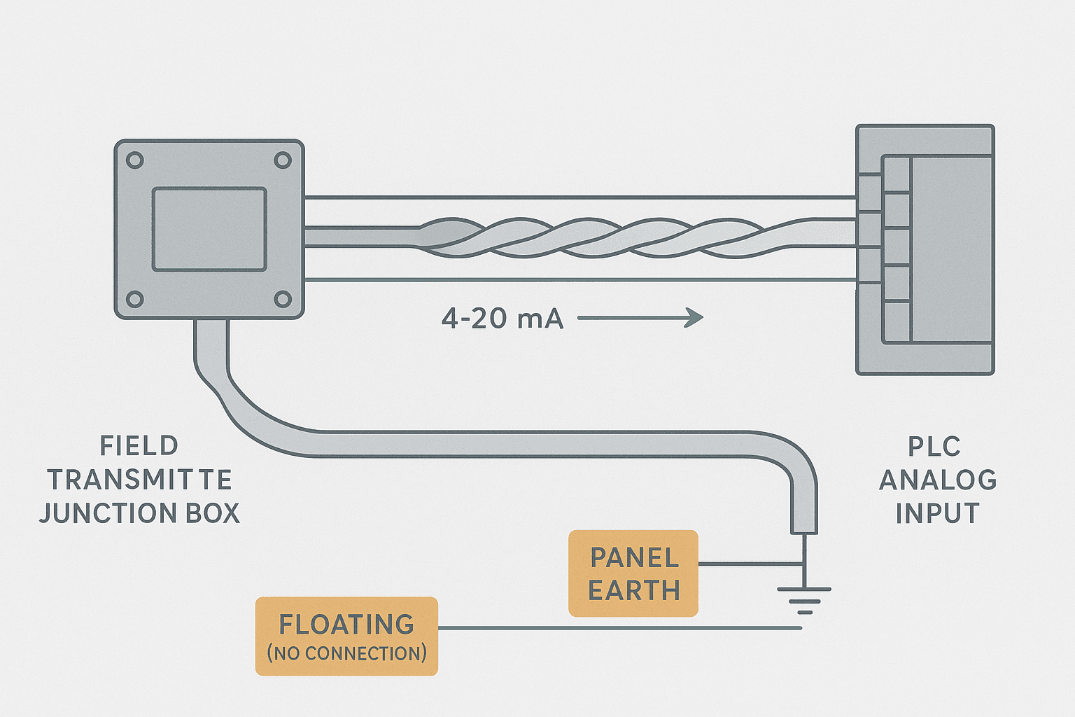
For DC and low-frequency analog signals, including 4-20 mA current loops, 0-10 V transmitters, RTD circuits, and thermocouples, ground the shield at one end only. The accepted practice is to terminate at the panel end, specifically at the analog input module's dedicated shield bar or the instrument earth bus. Leave the field end of the drain wire floating, trimmed back and sleeved with heat shrink so it cannot touch anything.
Why the panel end? Two reasons. First, it puts the shield reference at the cleanest, most controlled ground point you have. Second, it keeps the shield at a defined potential without creating a loop. The shield still picks up electric field interference and bleeds it to earth, but there is no closed circuit for induced currents to flow through.
Thermocouple Cables: An Extra Wrinkle
Thermocouple extension cables are shielded for the same reason as any analog cable. Ground the shield at the panel end, at the thermocouple input module or barrier. Do not ground at the thermocouple head, because the head is usually near a heat source or a motor, both of which are noisy. One thing people miss: the shield on a thermocouple cable must be insulated from the thermocouple sheath if the sheath is grounded. A grounded sheath connected to a separately grounded shield is a ground loop in disguise.
Cable Shield Grounding for Digital and High-Frequency Signals
This is where the rule flips. For high-frequency digital signals, including RS-485, PROFIBUS, EtherNet/IP, PROFINET, and any fieldbus running at hundreds of kilobits per second or faster, you want the shield grounded at both ends.
At high frequencies, the impedance of a single-ended shield rises to the point where it provides almost no protection against radiated magnetic interference. The shield works as a return path for high-frequency noise currents, and that only works if it is closed at both ends. Yes, there is a ground loop, but at high frequencies the inductance of the loop is high enough that common-mode currents are small, and the shielding benefit outweighs the ground loop risk.
The Frequency Boundary: Where to Draw the Line
A rough but practical rule: signals below about 1 kHz get single-ended shield grounding. Signals above roughly 100 kHz get both ends. Between 1 kHz and 100 kHz it depends on your specific noise environment and cable length. Encoder signals at 10 to 100 kHz often benefit from both-end grounding, but if you see ground loop problems, a small capacitor (10 nF to 100 nF, rated for your line voltage) at one end can break the low-frequency loop while maintaining the high-frequency path.
| Signal Type | Frequency Range | Shield Termination | Float Which End |
|---|---|---|---|
| 4-20 mA current loop | DC | Single end, panel side | Field end |
| 0-10 V voltage signal | DC to ~100 Hz | Single end, panel side | Field end |
| RTD (2/3/4-wire) | DC | Single end, panel side | Field end |
| Thermocouple | DC to ~10 Hz | Single end, panel side | Field end (isolate from sheath) |
| RS-485 / Modbus RTU | Up to ~10 Mbps | Both ends | Neither |
| PROFIBUS DP | 9.6 kbps to 12 Mbps | Both ends, continuous | Neither |
| PROFINET / EtherNet/IP | 100 Mbps to 1 Gbps | Both ends via plug shell | Neither |
| Incremental encoder | 1 kHz to ~1 MHz | Both ends (or cap at one) | Depends on noise |
How to Terminate Shields Properly in a Panel
A lot of the shield grounding failures I have seen come not from the wrong rule but from sloppy execution. Here are the practices that actually hold up:
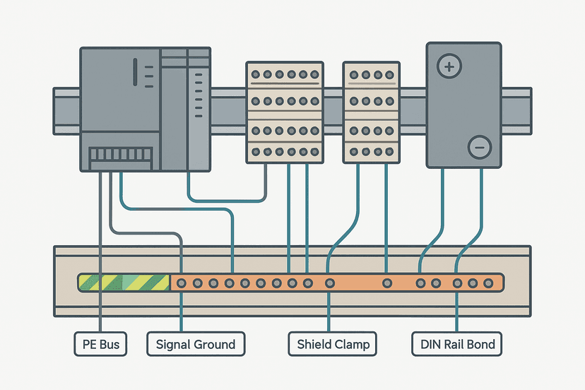
- Use a dedicated instrument earth (IE) bus bar, separate from the protective earth (PE) bus. Connect the IE bar to PE at a single point. This isolates sensitive analog shields from the noisy PE currents that flow from VFDs and contactors.
- Keep the unshielded tail between the end of the shield braid and the terminal block as short as possible. Under 50 mm is good. Over 150 mm and you are radiating. Use cable shield clamps or EMC glands at the panel entry gland plate to clamp the shield braid directly to the gland plate metalwork.
- Never loop the drain wire through multiple terminal blocks before connecting it to earth. One short run, straight to the shield bar.
- For multi-pair cables (common in process instrument home runs), each pair's shield should be grounded individually if the pairs carry different signals. Do not tie all drain wires together and then to earth through a single long conductor.
- If you are using an analog input module with a built-in shield bar (Siemens SM 331, Phoenix Contact AXL F AI, etc.), use it. Those bars are bonded directly to the module chassis and give you the lowest-impedance path.
- On the field side, insulate the floating drain wire with heat shrink. A bare drain wire touching a metal enclosure wall will ground the shield at the field end, creating exactly the loop you wanted to avoid.
What Happens When You Ground at Both Ends on an Analog Cable
You will see it on the trend. A clean 4-20 mA signal from a pressure transmitter will start showing a 50 Hz or 60 Hz sinusoidal ripple, typically a few counts on a 12-bit or 16-bit ADC. The ripple amplitude tracks the ground potential difference between the field instrument and the panel. In a plant with large motors or poor grounding infrastructure, that difference can be 0.5 V to 2 V, which on a 4-20 mA circuit with a 250-ohm burden resistor translates to 2 mA to 8 mA of interference current. That will make your PID loop hunt.
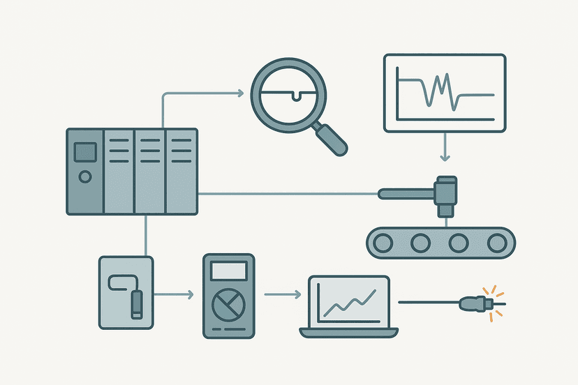
The fix is almost always simple: disconnect the field-end drain wire, sleeve it, and re-test. If the noise disappears, you had a ground loop. If it stays, the problem is something else, probably differential mode noise getting in through the signal conductors themselves, or a shielded cable with too-high shield resistance (check that the shield is actually intact and has low resistance end to end).
Cable Shield Grounding and the Analog Scaling Chain
Getting your shield termination right is the upstream prerequisite for accurate analog scaling. If you have noise on the raw ADC counts, no amount of averaging or filtering in the PLC will fully compensate. Fix the wiring first, then scale. If you need help with the scaling math once the signal is clean, the 4-20 mA Scaling Formula post covers the full calculation, and the analog scaling calculator will do the arithmetic for you.
Common Mistakes That Are Easy to Miss
- Grounding the shield at an intermediate junction box and leaving the panel end floating. This is backwards and gives you the worst of both worlds: a partial loop and a poorly referenced shield.
- Using standard PVC cable instead of a cable with a continuous foil or braid shield. A spiral-wrap serve shield has much higher optical coverage but can unwrap under repeated flexing. Use a foil-plus-drain-wire construction for fixed runs and a braid-plus-drain for moving cables.
- Connecting the shield to the signal negative terminal instead of a dedicated earth point. The signal negative (0 V return) is not earth unless you have intentionally bonded them, and even then the bond should be at one point only.
- Forgetting that conduit does not replace cable shielding. A steel conduit does attenuate magnetic fields, but only if it is properly bonded at both ends. Open conduit fittings or plastic conduit give you nothing.
- Running shielded analog cables in the same conduit or cable tray as 24 VDC switching outputs or 230 VAC power. Physical separation of at least 100 to 150 mm is required. Where they must cross, do it at 90 degrees.
A Note on Instrument Earth vs Protective Earth
This topic connects directly to panel grounding strategy, which is covered in depth in the Control Panel Grounding post. The short version: your shield earth bar should be bonded to PE at one point, at the main earth bus in the panel. Running a separate instrument earth all the way back to the building steel or the MCC ground bar, rather than connecting it at the panel earth bus, adds length and potential for interference pickup. Bond it locally and keep the bond conductor short and low-inductance, meaning wide and flat rather than long and thin.
If you have a site with genuinely terrible ground quality (old steel-framed buildings, sites with large welding equipment, or sites near high-voltage lines), you may need to consider optical isolation on analog inputs rather than fighting the ground potential difference with better shielding. Shielding has limits. Isolation removes the common-mode path entirely.
Frequently asked questions
Should a cable shield be grounded at one end or both ends?
What causes a ground loop in a shielded cable?
Where exactly should the shield drain wire connect inside a control panel?
Does shielding work without grounding?
Can I run analog and digital cables in the same cable tray?
Why does my 4-20 mA signal show 50 Hz noise even though the cable is shielded?
Learn this by building it
There is a PLC in this site. It runs a real scan engine, checks your logic against the same tests a working machine would fail, and needs no download and no account.
Open the exercisesFree, no signup, runs in your browser. See all 16 exercises.
Was this helpful?