How to Find a Ground Fault in a Control Panel
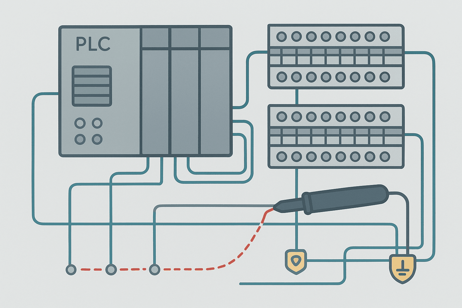
A ground fault annoys you quietly. The machine keeps running, but your GFCI trips, the isolation monitor alarm pings, or an intermittent input misbehaves. You spend twenty minutes staring at the panel before realising you do not have a plan. Let's fix that.
This guide focuses on the two voltage levels you deal with most in PLC control panels: 24 VDC control circuits and 120 VAC control circuits. The technique is slightly different for each, but the core method, isolate then measure, is the same.
What a Ground Fault Actually Is
A ground fault is an unintended low-impedance path between an energised conductor and the equipment ground (earth). In a healthy 24 VDC system both the positive and negative rails are floating above earth. Touch either rail to the panel chassis and you have a ground fault. In a 120 VAC system the neutral is typically bonded to ground at the transformer, so a ground fault on the line conductor creates a shock and fire hazard.
The failure mode is usually one of three things: chafed wire insulation touching a metal edge, a screw terminal over-tightened until it cuts through wire insulation, or moisture inside a conduit or enclosure. Connector pins pushed too far back into their housings are a sneaky fourth one that comes up more than you would expect.
Tools You Need
- A digital multimeter with a 10 MΩ or higher input impedance (Fluke 117 or equivalent)
- A 500 V insulation resistance tester (megohmmeter) for 120 VAC circuits where you want hard numbers
- Wiring diagrams for the panel (if you do not have them, you are doing this the hard way)
- Needle-nose pliers and a small flat screwdriver for pulling wires from terminals
- Tape flags or clip-on wire markers to track what you have already checked
How to Find a Ground Fault: The Isolation Method
The fastest reliable method is binary isolation: split the circuit in half, test each half, discard the clean half, split again. You can locate a fault in a 64-wire panel in six splits. Here is how that plays out in practice.
Step 1: Confirm the Fault Exists
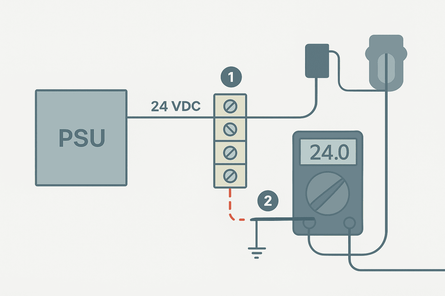
Set your multimeter to DC volts. With the 24 VDC PSU energised, measure from the positive bus to the chassis ground lug, then from the negative bus to chassis ground. In a healthy floating system both readings should be near zero or highly unstable (the meter's internal impedance is the only path, so you see noise). A steady reading of a few volts means one side is grounded. A reading close to the full supply voltage means the other side is grounded.
For 120 VAC: measure line to ground and neutral to ground. Line to ground should read roughly 120 VAC. Neutral to ground should read less than 2 VAC at the panel if your neutral-ground bond is clean. A high neutral-to-ground reading (10 V or more) points to a neutral conductor fault or a bad bond at the transformer.
Step 2: Identify Which Circuit Branch Has the Fault
Power down, then remove all field wiring from the output terminal strip. Re-energise and measure again. If the fault reading disappears, the fault is in the field wiring or field devices, not inside the panel. If the fault reading stays, the fault is inside the panel itself.
Now reconnect field wiring one circuit branch at a time, measuring after each reconnection. When the fault reappears, that branch is your culprit. Mark it and move on.
Step 3: Walk the Suspect Branch Wire by Wire
Power down. Disconnect both ends of the suspect branch. Set your multimeter to the resistance function (or use your megohmmeter at 500 V for 120 VAC wiring). Measure from the wire conductor to the nearest ground lug. A healthy wire reads open (OL on most meters). A faulted wire reads anywhere from a few ohms to a few kilohms depending on how bad the insulation damage is.
If you get a marginal reading, say 50 kilohms to a megohm, it may only show up under normal operating temperature. That is why a megohmmeter at 500 V is more revealing than a low-voltage ohmmeter: it stresses the insulation the way the actual circuit does.
Step 4: Find the Physical Fault Location
Once you know which wire is faulted, flex it gently while watching your meter. A reading that changes as you bend the wire near a specific point tells you the exact location of the damage. Common spots: where the wire exits a drag chain, at the entry point to a connector, where it passes through a metal grommet that someone forgot to install, and at any 90-degree bend that was made too tight.
In conduit runs, water ingress is the usual culprit. Pull the wire out at the nearest junction box. If the wire looks fine but the reading is still bad, the insulation damage is internal and you cannot see it. Replace the run.
Ground Fault Hunting in 24 VDC PLC I/O Circuits
24 VDC I/O circuits have one extra complication: the PLC itself. Some PLC input cards have a pull-up or pull-down resistor to the 0V rail, which means you will measure a low resistance from certain I/O terminals to the negative bus even in a healthy system. Check the card datasheet before you conclude there is a fault.
Siemens S7-1200 and S7-1500 input cards, for example, have internal 10 kilohm pull-down resistors on each channel. If you measure from an input terminal to chassis ground with a standard ohmmeter you will read roughly 10 kilohms plus whatever the loop resistance is. That is normal. The ground fault to look for is much lower, typically below 1 kilohm.
Common Ground Fault Locations and Their Signatures
| Location | Typical Reading | How to Confirm |
|---|---|---|
| Chafed wire in drag chain | 5 to 200 Ω, changes when chain moves | Flex chain, watch meter |
| Water in conduit | 1 to 50 kΩ, often intermittent with temperature | Pull wire, dry conduit, retest |
| Damaged cable gland seal | 10 to 100 kΩ, worse after rain | Inspect gland, megohm test after drying |
| Over-torqued screw terminal cutting insulation | Near 0 Ω, steady | Loosen terminal, inspect wire |
| Connector pin pushed back into housing | Intermittent, changes with vibration | Push-pull each pin, inspect housing |
| Failed sensor with internal short | Steady, low resistance | Disconnect sensor, fault clears instantly |
After You Fix It: Verify and Prevent Recurrence
After the repair, re-energise and repeat your original bus-to-chassis measurement to confirm the fault is gone. Then document exactly what you found: the wire number, the physical location, and the root cause. A chafed wire in a drag chain means the cable clamp spacing is wrong or the bend radius is too tight. Fix the root cause or you will be back in six months.
If you do not already have a 24 VDC isolation monitor in this panel, this is a good time to add one. Devices like the Bender ISOMETER iso165C or the Phoenix Contact EMD-SL-C-UV-10 sit on the bus, continuously measure insulation resistance, and trigger an alarm the moment resistance drops below your threshold, say 20 kilohms, before the fault becomes a zero-ohm hard fault that takes out the PSU or fires a nuisance E-stop.
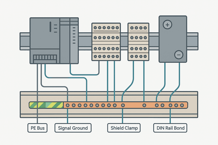
Good panel grounding practices also reduce the chance of a fault causing real damage when one does occur. The Control Panel Grounding: The Right Way to Do It post covers the bonding and earthing fundamentals if you want to tighten that up while you have the panel open.
Quick Reference: Ground Fault Checklist
- Confirm fault: measure each bus rail to chassis ground. Note which rail shows a reading.
- Disconnect all field wiring. Remeasure. Fault gone = field side. Fault stays = panel side.
- Reconnect branches one at a time. Fault reappears = that branch is suspect.
- Power down. Disconnect suspect wire at both ends. Ohmmeter from conductor to chassis. Low reading = faulted wire.
- Flex the wire along its run. Reading changes at a specific spot = physical damage there.
- Repair or replace the wire/cable. Remeasure to confirm clean.
- Document root cause and fix the mechanical reason, not just the symptom.
Frequently asked questions
Can I find a ground fault with just a regular multimeter?
Why does my 24 VDC ground fault not trip a breaker?
How do I find an intermittent ground fault that disappears when I look for it?
What is the minimum acceptable insulation resistance for a 24 VDC control circuit?
Does a ground fault affect PLC inputs differently than outputs?
What is the difference between a ground fault and a short circuit?
Learn this by building it
There is a PLC in this site. It runs a real scan engine, checks your logic against the same tests a working machine would fail, and needs no download and no account.
Open the exercisesFree, no signup, runs in your browser. See all 16 exercises.
Was this helpful?