Electric Actuator Sizing: Torque, Thrust and Duty
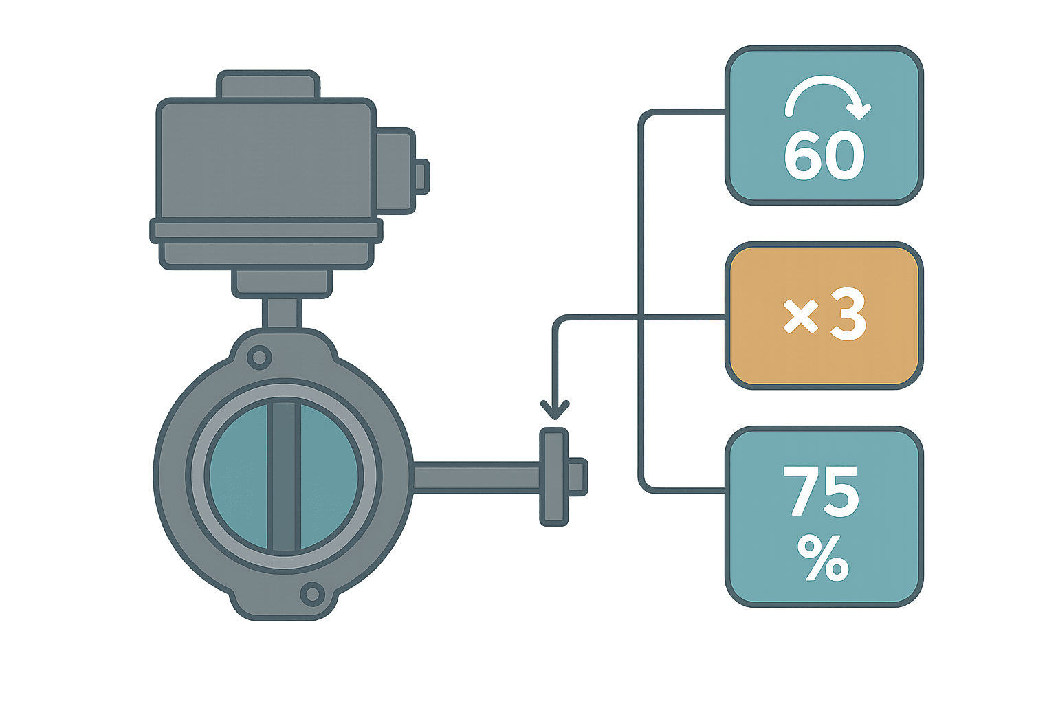
Undersized electric actuators are one of those failure modes that nobody admits to until the motor burns out three months after commissioning. You get the valve spec, look at the actuator catalogue, pick something that looks right on paper, and then the thing stalls every time the line pressure spikes. Getting electric actuator sizing right means working through torque or thrust requirements methodically, not guessing from a valve DN size alone.
Rotary vs Linear: Which Calculation Applies?
Electric actuators come in two fundamental types and each has its own sizing path. Rotary actuators (quarter-turn or multi-turn) produce torque in Newton-metres and drive butterfly valves, ball valves, and plug valves. Linear actuators produce thrust in Newtons or kilonewtons and drive gate valves, globe valves, dampers with linkages, or mechanical slides. Mixing up which number matters is a surprisingly common mistake, especially when a datasheet lists both and you grab the wrong column.
Electric Actuator Sizing for Rotary Valves
For butterfly and ball valves, the actuator must overcome breakaway torque (unseating the disc or ball from a closed position against differential pressure), running torque (rotating through the travel), and seating torque (closing firmly enough to seal). Of these, breakaway torque is almost always the worst case.
Most valve manufacturers publish a torque table in their datasheet, broken down by valve size and differential pressure in bar. If you have that number, use it directly. If you don't, the general formula for a rubber-seated butterfly valve is:
T_breakaway (N·m) = C_v × D³ × ΔP

Where:
  D   = valve bore diameter in metres
  ΔP  = differential pressure across the closed valve in bar
  C_v = valve-specific torque coefficient (typically 0.02 to 0.07 for rubber-seated butterfly)

Example:
  D   = 0.200 m  (DN200 butterfly valve)
  ΔP  = 10 bar
  C_v = 0.04

  T_breakaway = 0.04 × (0.200)³ × 10 × 100 000 Pa/bar
              = 0.04 × 0.008 × 1 000 000
= 320 N·mOnce you have breakaway torque, apply a safety factor before selecting the actuator. A minimum of 1.25 is common practice. For applications with high cycle frequency, corrosive media, or significant temperature variation, 1.5 is more sensible. Some petrochemical specs mandate 2.0.
So for the example above: 320 N·m × 1.5 = 480 N·m minimum actuator output torque. You'd pick the next standard size up from the catalogue, which might be a 500 N·m or 550 N·m unit.
Multi-Turn Actuators for Gate and Globe Valves
Multi-turn actuators drive stems that require many full rotations to open or close. Here you still need torque at the actuator output shaft, but the valve datasheet usually gives you stem thrust in kN and a stem lead in mm/revolution. Convert thrust to torque using:
T (N·m) = (F × L) / (2 × π × η)

Where:
  F   = required stem thrust in Newtons
  L   = stem lead (linear travel per revolution) in metres
  η   = stem/nut efficiency (typically 0.25 to 0.40 for an Acme thread)

Example:
  F   = 50 000 N  (50 kN gate valve closing thrust)
  L   = 0.010 m   (10 mm lead)
  η   = 0.30

  T = (50 000 × 0.010) / (2 × 3.1416 × 0.30)
    = 500 / 1.885
    = 265 N·m
Electric Actuator Sizing for Linear Thrust
Rod-style linear actuators output force directly in Newtons, so sizing is more direct. Add up the forces the actuator must overcome:
- Pressure load: differential pressure across the plug or disc multiplied by the seat area. A 50 mm diameter plug at 6 bar sees roughly 50 × 6 = 1 178 N just from pressure.
- Spring return force: if the valve or damper has a spring return, the actuator must overcome full spring compression at end of stroke.
- Packing friction: typically 10 to 20% of the pressure load for new PTFE packing, more for graphite packing and higher temperatures.
- Gravity load: if the rod is vertical and the load is not counterbalanced, include the weight of the moving assembly.
Sum those, apply your safety factor (again, 1.25 to 1.5 is typical), and compare against the actuator's rated thrust at the required stroke speed. Actuator catalogues usually give a thrust-vs-speed curve because increasing speed reduces available force from the same motor.
Duty Cycle: The Part Everyone Forgets
Torque and thrust get the attention, but duty cycle kills more actuators than undersizing ever does. Electric actuator motors run hot. Every stroke heats the windings, and if the actuator cycles faster than it can cool down, the insulation degrades and the motor fails.
Duty cycle is expressed as a percentage of on-time over a defined period, or sometimes as a maximum number of operations per hour. Common ratings you'll see on datasheets:
| Duty Rating | Typical Definition | Typical Application |
|---|---|---|
| S2 15 min | One continuous run up to 15 minutes, then cool-down | Isolation valves that open once per shift |
| S4 25% | 25% on-time in a 10-minute period | Process control with moderate cycling |
| S4 50% | 50% on-time in a 10-minute period | Frequent modulating control duty |
| Continuous (S1) | 100% on-time indefinitely | Slow modulating or positioner duty on large valves |
| 60 ops/hr | Maximum 60 full open-close cycles per hour | Packaging or fast-cycling process lines |
For a valve that opens and closes a few times per shift, almost any duty rating will do. For a control valve on a fast PID loop that hunts and drives the actuator back and forth every few seconds, you need either an S1-rated actuator or a proper positioner with a deadband setting that stops unnecessary hunting. I've seen a perfectly sized 300 N·m actuator fail in six weeks on a pH control loop because nobody set a 1% deadband on the positioner.
Speed, Stroke Time and Process Requirements
Actuator speed matters for two reasons: process safety and water hammer. On a 90-degree quarter-turn actuator, a typical range is 5 to 60 seconds for a full stroke. For isolation duty, faster is usually fine. For pump discharge valves on long pipelines, a 30-second or slower stroke time prevents water hammer on closure.
Some actuator families let you adjust stroke time via a built-in triac controller or by changing the gear ratio module. Others are fixed speed. Confirm which you have before commissioning. Rockwell Automation's ICSF series, Rotork's IQ3 family, and Auma's SA/SAR range all offer adjustable speed options, but the method varies and you need to read the specific manual.
Putting It Together: A Sizing Checklist
Before you call up the catalogue, gather these numbers. Missing even one means you're guessing.
- Valve type and size (DN or NPS, and disc/ball/gate geometry)
- Maximum differential pressure across the valve in the closed position
- Fluid type (clean water, slurry, gas, viscous liquid) because friction factors vary
- Valve manufacturer's published torque or thrust at maximum ΔP
- Required stroke time or maximum acceptable closure speed
- Number of operations per hour at steady state and during batch transitions
- Control mode: on/off, or proportional with 4-20 mA positioner
- Environment: temperature range, ingress protection needed (IP67, IP68, Ex zone)
- Fail-safe requirement: fail-open, fail-close, or fail-in-place (spring return vs battery backup)
Safety Factor: How Much Is Enough?
The right safety factor depends on how well you know the application. If the valve manufacturer gives you a torque curve verified by test, 1.25 is usually defensible. If you're estimating from a formula because you don't have the datasheet, use 1.5 minimum. If the valve sees corrosive media, high temperatures, or has been in service for years and is likely to have increased stem friction, 2.0 is not overkill.
One thing I always check: will the actuator ever need to unseat the valve after a long idle period? Valves that sit closed for months can stick significantly beyond the normal breakaway torque value. For such applications, some engineers add a 10 to 20% extra margin on top of whatever safety factor they calculated.
On the related topic of pneumatic cylinders, we've covered bore and force calculations in detail over at Pneumatic Cylinder Sizing: Force, Bore and Stroke. The underlying approach is similar but the duty cycle concern is essentially absent since compressed air doesn't heat up a pneumatic actuator the way electric current heats a motor.
PLC Integration Points for Electric Actuators
Once you've sized the actuator correctly, the PLC interface is what ties it to the control system. Most modern electric actuators offer:
- Discrete I/O: Open and Close command inputs (24 VDC), plus Open and Closed limit switch feedback outputs. Simple and reliable for on/off service.
- 4-20 mA position command and feedback: for proportional control. The positioner inside the actuator closes its own inner loop; the PLC just sends a setpoint.
- Fieldbus (PROFIBUS, DeviceNet, FOUNDATION Fieldbus, HART): for diagnostic-rich integration including torque monitoring, temperature, and partial stroke test results.
- Torque trip outputs: a discrete output that goes active if the actuator trips on overtorque. Wire this to a PLC input and alarm it. Ignoring repeated torque trips guarantees mechanical damage.
For the 4-20 mA scaling between PLC raw counts and valve position percentage, the analog scaling calculator handles the conversion cleanly without needing to do the arithmetic manually every time.
Common Sizing Mistakes and How to Avoid Them
- Sizing from valve bore alone. A DN150 valve can need anywhere from 100 N·m to over 600 N·m depending on pressure class, seat type and media. Always use a pressure-specific torque value.
- Ignoring the spring return force. A fail-closed spring return actuator must add the spring force to the process load when closing. Some actuators need the spring force subtracted when opening. Check the direction.
- Choosing S4 25% for a proportional control loop. If a PID controller is active, assume worst-case duty and specify accordingly, or add a positioner deadband to limit travel.
- Not accounting for the gearbox. If you're adding an intermediate gearbox between the actuator and the valve stem, recalculate the torque at the valve shaft accounting for gearbox efficiency (typically 0.85 to 0.95 per stage).
- Forgetting the environment. An IP65 actuator on a wash-down application or in a coastal environment will fail. Specify IP67 or IP68 where water ingress is realistic.
Frequently asked questions
How do I find the required torque for an electric actuator if the valve has no datasheet?
What safety factor should I use for electric actuator sizing?
What is duty cycle on an electric actuator and why does it matter?
What is the difference between sizing a rotary and a linear electric actuator?
Can I use the same electric actuator for both on/off and proportional control?
How does fail-safe mode affect electric actuator sizing?
Learn this by building it
There is a PLC in this site. It runs a real scan engine, checks your logic against the same tests a working machine would fail, and needs no download and no account.
Open the exercisesFree, no signup, runs in your browser. See all 16 exercises.
Was this helpful?