Keyence KV Studio: A Practical Getting-Started Guide
If your first encounter with Keyence KV Studio is a blank project and a 400-page PDF manual, you're not alone. KV Studio is actually a well-designed piece of software once you understand its logic, but the learning curve is steeper than it needs to be because the address system and project structure are different from anything you've used on Rockwell or Siemens. This guide skips the sales pitch and gets into the specifics: software setup, the device address map, how to structure a project, and a working ladder example you can actually run.
KV Studio Software: Download, Versions and What's Free
KV Studio is free to download from Keyence's website. Version 12 (the current release as of 2024) supports the full KV series: KV-8000, KV-7500, KV-5500, KV-5000, KV-3000 and the smaller KV-1000 and KV-700 units. The simulator is bundled in, so you can run and debug programs without hardware. That's a genuine advantage over some competitors who charge for offline simulation.
The install is roughly 1.5 GB and requires Windows 10 or 11 (64-bit). One thing that trips people up: you need to install the USB driver separately if you want USB programming access to the CPU. It ships in the same download package but as a separate installer in the Driver subfolder. Skip it and you'll spend 20 minutes wondering why Device Manager shows an unknown device when you plug in the KV-8000.
KV Studio Address System: Devices, Not Variables
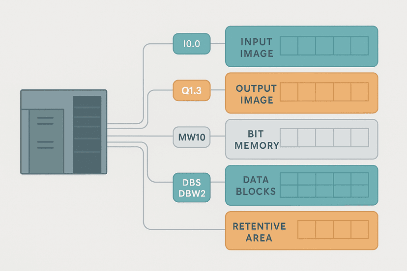
This is where KV Studio feels foreign if you're coming from Studio 5000 or TIA Portal. Keyence uses a device-based address system rather than symbolic tag databases. Every memory location has a device letter prefix followed by a number. You can add labels (essentially aliases) on top, but the underlying program references device addresses directly.
| Device | Type | Typical Range | Notes |
|---|---|---|---|
| R | Internal relay (bit) | R00000 to R99915 | General-purpose, non-retentive by default |
| MR | Internal relay (bit) | MR00000 to MR99915 | Retentive across power cycle |
| CR | Control relay | CR2000 to CR3915 | System flags, read-only in most cases |
| DM | Data memory (word) | DM00000 to DM65535 | 16-bit word, non-retentive by default |
| FM | File memory (word) | FM00000 to FM32767 | Retentive word memory |
| T | Timer | T0000 to T3999 | 100 ms resolution by default |
| C | Counter | C0000 to C3999 | Up counter, 0 to 65535 |
| @ | Index modifier | Used with DM or R | Indirect addressing like DM[@AT0] |
Physical I/O follows a slot-based scheme. Unit 0 is always the CPU. The first expansion unit to the right is Unit 1, the next is Unit 2, and so on. A 16-point input module in Unit 1 occupies 00000 to 00015 in the I/O area. A 16-point output module in Unit 2 starts at 00100 (Unit 2 prefix 001, points 00 to 15). The prefix increments by 100 per unit position. Get that wrong and your physical wiring won't match your program addresses.
Setting Up a New Project Step by Step
Open KV Studio and go to File > New Project. You'll be asked to pick a CPU model first. Choose carefully: selecting KV-5500 when you have a KV-8000 on the bench means you'll lose access to the 8000's expanded instruction set and won't be able to download the project. Once you pick the CPU, you define the unit configuration. This is the Unit Editor, and it's worth spending five minutes getting it right before you write a single rung.
- In the Unit Editor, drag expansion units from the module library on the left into the rack view. Match the physical order on your DIN rail.
- Double-click each I/O module to set its I/O type (NPN sinking or PNP sourcing) if the module supports it. Some KV input modules are configurable per group of 8 points.
- Add any communication units (KV-EP21V for EtherNet/IP, KV-XLE02 for PROFINET, etc.) in the correct slot position.
- Click Compile in the Unit Editor toolbar to check for conflicts. KV Studio will flag if two units claim overlapping address ranges.
- Save the project. The unit configuration is stored in the project file, not on the CPU, so a backup of the .kvpx file includes the full hardware config.
KV Studio Ladder Editor: What Feels Different
The ladder editor works the way most do: click to place contacts, coils, and function blocks. A few things are worth calling out specifically.
Labels vs device addresses. You can type a label name (e.g., Conveyor_Run) directly into a coil and KV Studio will create a label automatically and assign it to the next free R device. Or you can type R00100 directly. Either works, but mixing the two in the same program makes maintenance harder. Pick one convention and stick to it. In my experience, labels are worth it for anything customer-facing; raw device addresses are fine for internal test programs.
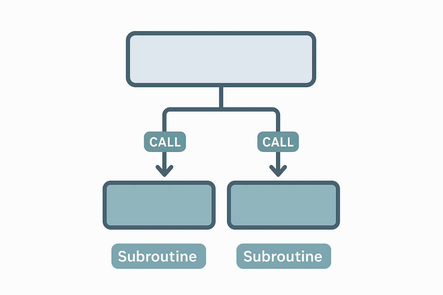
Subroutines and scan structure. KV Studio organizes programs into a main scan (Program 0) and up to 512 subroutines. You call subroutines with the CALL instruction. Unlike some platforms where subroutines are always executed in order, KV subroutines only run when explicitly called, which means you can conditionally execute whole blocks of logic. This is powerful, but it means you need to be deliberate about where you put your I/O update rungs.
Timer resolution. KV timers default to 100 ms per tick, so a timer set to K50 times out at 5 seconds. You can change resolution to 10 ms or 1 ms per timer in the timer settings dialog, but you have to do this individually per timer number. There's no global setting. Miss this and you'll wonder why your 500 ms timeout fires in 50 seconds.
Keyence KV Studio Ladder Logic Example
Here's a practical example: a two-hand control interlock for a press application. Both push buttons must be pressed within 500 ms of each other, or the press output is inhibited. This is a classic KV application in small press and stamping cells. The logic uses two timers and a window-detection relay.
Two-Hand Control Timing Interlock (Keyence KV Studio). Ladder logic (4 rungs): Rung 0: examine if PB_Left_Hand is on (XIC), then TON on T0000. Rung 1: examine if PB_Right_Hand is on (XIC), then TON on T0001. Rung 2: examine if PB_Left_Hand is on (XIC), then examine if PB_Right_Hand is on (XIC), then examine if T0000.DN is off (XIO), then examine if T0001.DN is off (XIO), then energize output TwoHand_OK (OTE). Rung 3: examine if TwoHand_OK is on (XIC), then examine if Press_Fault is off (XIO), then energize output Press_Output (OTE). T0000 and T0001 are set to 10 ms resolution, K5 = 50 ms window. If either hand is released before the other is pressed, one timer times out and TwoHand_OK drops. Press_Output only energizes when both hands are held and neither timer has expired. This enforces simultaneous press within 50 ms without a dedicated safety relay for the timing function (the safety relay still handles the E-stop chain separately).
The diagram above evaluates one scan. Run these exact rungs on a real scan cycle to watch the latching and the timers behave.
Run this in the simulatorConnecting to the PLC: USB vs Ethernet
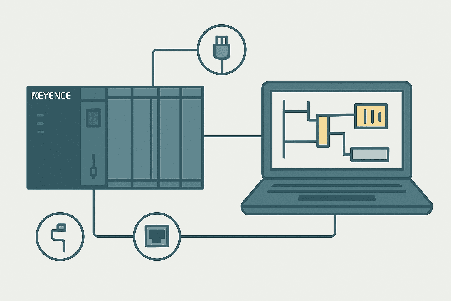
USB is the easiest first connection. Plug in the USB-B cable, let Windows install the driver (or install it manually from the Driver folder as mentioned earlier), and in KV Studio go to Communication > Communication Settings and select USB. Click Connect and you should see the CPU model and current program version in the status bar.
Ethernet requires setting the CPU's IP address first, which you do over USB. Go to Communication > Unit Editor > CPU > Ethernet Settings and enter the IP, subnet mask and gateway. Write that to the CPU, then switch Communication Settings to Ethernet and enter the same IP. The KV-8000 defaults to 192.168.0.1 with a subnet of 255.255.255.0, which conflicts with almost every office network. Change it before you bring the PLC onto any shared infrastructure.
Monitoring, Forcing and the Watch Window
KV Studio's monitor mode works the way you'd expect: energized contacts show highlighted, coil states are visible inline. The Watch Window (called Device Monitor in KV Studio) lets you add any device address or label and watch its current value. You can force bits on or off by right-clicking in the Device Monitor and selecting Force On or Force Off. Forces are visually flagged in the ladder editor with a small F indicator, so you can't easily forget you've left something forced.
One feature I actually like: the Trend Monitor records device values over time directly in KV Studio without needing external SCADA software. For commissioning a motion profile or timing sequence, being able to plot T0000.ACC against a sensor bit without leaving the programming tool saves real time.
KV Studio and Modbus TCP
The KV-8000 and KV-5500 CPUs both support Modbus TCP server mode natively, no additional module needed. You map KV device addresses to Modbus registers in the Communication > Modbus TCP settings. DM registers map to Holding Registers starting at 40001, and R relays map to Coils starting at 00001. The mapping is fixed by device type, which is simple but means you need to lay out your DM and R memory with the Modbus map in mind from the start. See our Modbus RTU protocol deep-dive if you need a refresher on how Modbus register types work before configuring this.
Common Gotchas When Starting with KV Studio
- Timer resolution is per-timer, not global. Set it before you write the timer rung, not after.
- The Unit Editor config must match the physical rack. A mismatch causes a hardware error on download, not on compile.
- Labels and device addresses share the same namespace. If you name a label 'R00100', KV Studio will create confusion. Use descriptive names that don't look like device addresses.
- The simulator does not emulate scan-time effects on fast pulse inputs. A 1 ms pulse on a digital input may be missed in simulation but caught on real hardware, or vice versa depending on your scan time.
- KV Studio ver 11 and ver 12 project files are not backward compatible. If a customer sends you a ver 12 project and you have ver 11 installed, you can't open it. Always check the version before a site visit.
- Retentive memory (MR, FM) retains values through power cycles by default. If you're using MR relays for flags that should clear on startup, add a startup subroutine that resets them explicitly.
KV Studio is a capable environment and the KV-8000 is genuinely a high-performance CPU (up to 400K steps, 0.98 ns/step execution). The learning curve is mostly about unlearning assumptions from other platforms. Once you internalize the device address map and the unit-based I/O scheme, programming it feels natural. If you're also handling the sensor side of a Keyence installation, the KV series integrates cleanly with Keyence's IV3 vision sensors and LJ-X8000 laser profilers via dedicated function blocks, which is a real time-saver over generic serial integrations.
Frequently asked questions
Is Keyence KV Studio free to download and use?
Which Keyence PLCs does KV Studio support?
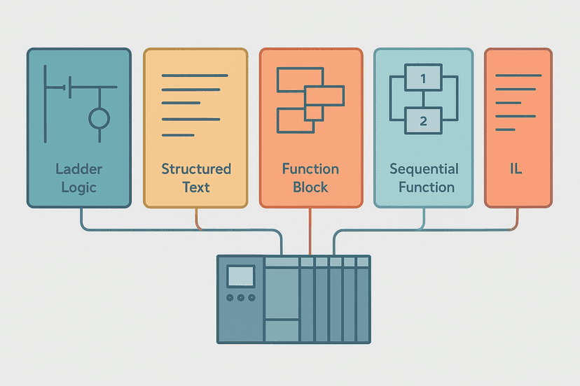
What programming languages does KV Studio support?
How do I change the timer resolution in KV Studio?
Can KV Studio connect to third-party SCADA systems?
What is the difference between R relays and MR relays in KV Studio?
Learn this by building it
There is a PLC in this site. It runs a real scan engine, checks your logic against the same tests a working machine would fail, and needs no download and no account.
Open the exercisesFree, no signup, runs in your browser. See all 16 exercises.
Was this helpful?