PLC Memory and Addressing Explained
Every value your PLC program reads or writes lives somewhere in memory. Get that address wrong and your conveyor runs backwards, your counter never resets, or you corrupt a recipe value from a completely unrelated rung. PLC memory addressing is one of those fundamentals that experienced engineers take for granted, but it trips up programmers at every level, especially when switching between vendor platforms.
This post covers how PLC memory is actually structured, how the major addressing styles differ, and where the real gotchas live. We will work through Siemens S7/TIA Portal, Rockwell Studio 5000 (ControlLogix/CompactLogix), and CODESYS-based systems because those three together cover most of the market.
PLC Memory Addressing: The Big Picture
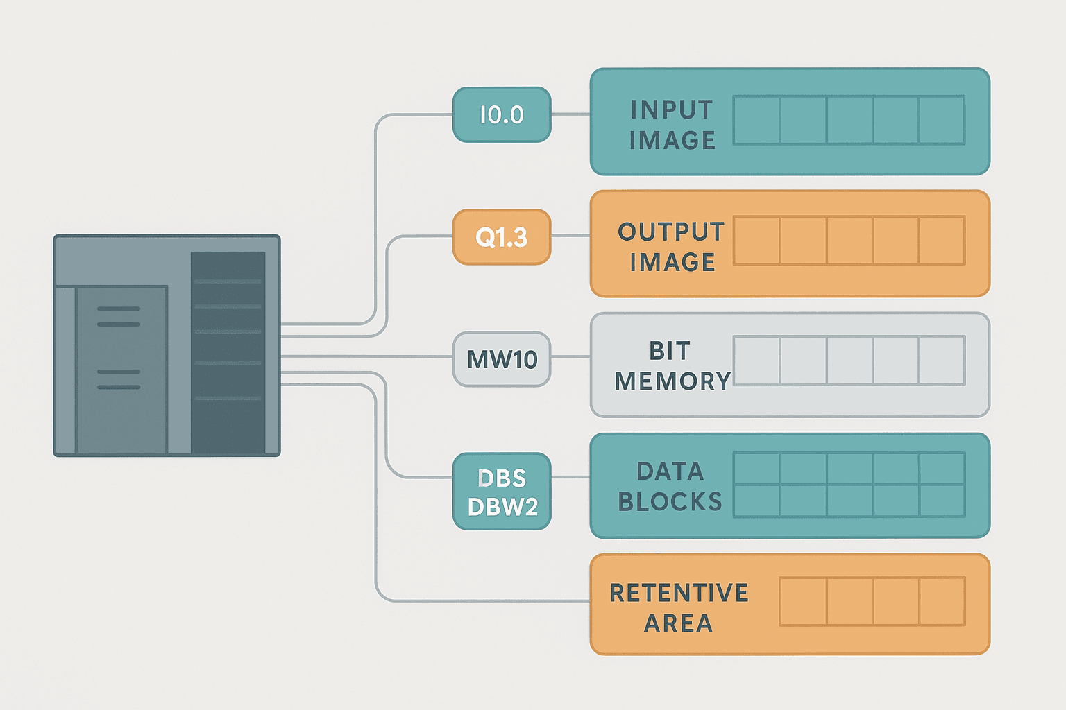
A PLC holds data in several distinct memory regions. The processor copies the physical state of field wiring into an input image table at the start of each scan, executes your logic against that snapshot, then writes results to an output image table that drives the physical outputs at the end of the scan. Everything else, timers, counters, internal flags, recipe data, sits in various internal memory regions depending on the platform.
There are two broad addressing philosophies across the industry: absolute addressing (you reference a physical byte/bit location directly, like I0.3 or N7:0) and symbolic/tag-based addressing (you reference a named tag, like Pump1_Run, and the compiler assigns the memory location). Modern platforms push heavily toward symbolic addressing, but plenty of installed S7-300 and SLC-500 systems still use absolute addressing, and understanding both saves you when you are staring at legacy code at 2am.
Siemens S7 Absolute Addressing in Detail
Siemens S7 addressing follows a consistent Area + Data Size + Byte Number . Bit Number pattern. Once you know the pattern it becomes readable fast.
| Area | Prefix | Example (Bit) | Example (Word) | Notes |
|---|---|---|---|---|
| Input image | I | I0.3 | IW4 | Read-only in most contexts; refreshed each scan |
| Output image | Q | Q1.7 | QW2 | Written to physical outputs end of scan |
| Bit memory (flags) | M | M10.5 | MW20, MD100 | Internal work area, not wired to field |
| Data block | DB | DB5.DBX2.0 | DB5.DBW4, DB5.DBD8 | Structured storage, shared or instance |
| Temp (local stack) | L | L0.0 | LW2 | Valid only within current OB/FC/FB call |
| Timer | T | T5 | (varies) | Classic S7 only; TIA uses IEC timers in DBs |
| Counter | C | C10 | (varies) | Classic S7 only; TIA uses IEC counters in DBs |
The size specifier tells you how many bits you are reading: none (bit), B (byte, 8 bits), W (word, 16 bits), D (double word, 32 bits). So MW10 is a 16-bit word starting at byte 10 of M memory, and MD10 is a 32-bit value starting at the same byte. Overlapping those two in the same program is a classic way to corrupt data without any compiler warning.
MW10 covers bytes 10 and 11. MW12 starts at byte 12 and is safe. But MW11 overlaps with byte 11 of MW10. The compiler will not stop you. I have seen this flatten a whole day of commissioning because a timer preset stored in MW10 was being silently overwritten by a status word at MW11.In TIA Portal with S7-1200 and S7-1500, Siemens strongly encourages symbolic (tag-based) programming. You still can use absolute addressing with the % prefix (e.g. %I0.3), but the default is to name your tags in the PLC tag table and let TIA assign addresses. For structured data you use Data Blocks (DBs), and the compiler handles the byte layout. If you tick "Optimized block access" on a DB (the default in TIA Portal), the CPU arranges data for performance and you cannot use absolute addressing into that DB at all. Turn off optimized access if you need Modbus register mapping or HMI absolute addressing into the DB.
Rockwell Studio 5000: Tag-Based Addressing from the Ground Up
ControlLogix and CompactLogix (Studio 5000) went fully tag-based from day one. There is no M-memory or fixed I/O image table address you reference directly in your rungs. Instead you create a tag, give it a name and a data type, and the controller manages the memory. This is cleaner to read but it introduces its own traps.
Tag Scope: Controller vs. Program
Every tag in Studio 5000 has a scope. Controller-scope tags are global, visible to every program and routine in the project. Program-scope tags are local to a single program and invisible outside it. Forgetting this is a real source of bugs: you create Pump1_Run as a program-scope tag in Program A, then try to reference it from Program B's routine and get a fault. The fix is to promote the tag to controller scope or use a produced/consumed tag, but first you need to recognise the scope problem.
I/O tags are always controller-scope and follow the pattern LocalSlot:I.Data.x or, for remote I/O, Rack:Slot:I.Data.x. For example, a digital input from a 1756-IB16 in slot 3 might be Local:3:I.Data.0 for the first input bit. You alias these to friendly names like Pump1_RunFeedback in the alias file, which is best practice. Editing the hardware later only requires updating the alias, not hunting through every rung.
Data Types and Bit-Within-Integer Addressing
Studio 5000 has proper data types: BOOL, SINT (8-bit), INT (16-bit), DINT (32-bit), REAL (32-bit float), LINT (64-bit), strings, arrays and user-defined types (UDTs). You can access individual bits of an integer tag with dot notation: MyDINT.3 gives you bit 3 of a DINT. This is handy for packing status flags into a single word for Modbus or HMI. But watch the bit numbering: Rockwell counts from bit 0 (LSB), so .0 is the least significant bit.
Motor_Type UDT with members Run, Fault, Speed_RPM, FaultCode and use it for every motor in the plant. Your HMI can then browse Motor_Array[0].Fault, Motor_Array[1].Fault etc. without copying tags one by one. Maintenance engineers can find data intuitively too.CODESYS and IEC 61131-3 Addressing
CODESYS (used on Beckhoff TwinCAT, Phoenix Contact PLCnext, Wago, many others) follows IEC 61131-3 directly. Variables are declared in programs, function blocks, or globally in the Global Variable List (GVL). You can optionally bind a variable to a physical address using the AT % syntax:
VAR_GLOBAL
    (* Digital inputs bound to physical I/O *)
    Pump1_RunFB    AT %IX0.0 : BOOL;   (* Input, byte 0, bit 0 *)
    Pump2_RunFB    AT %IX0.1 : BOOL;
    TankLevel_High AT %IX1.3 : BOOL;

    (* Digital outputs *)
    Pump1_RunCmd   AT %QX0.0 : BOOL;   (* Output, byte 0, bit 0 *)
    Pump2_RunCmd   AT %QX0.1 : BOOL;

    (* Analog input: 16-bit word from channel 0 *)
    FlowSensor_Raw AT %IW2   : WORD;   (* Input word, byte 2 *)

    (* Internal flag, no physical binding *)
    System_Ready   : BOOL;
END_VAR
The %I / %Q / %M prefixes map to inputs, outputs and memory respectively. The size character X means bit, B byte, W word (16-bit), D double word (32-bit). So %QD4 is a 32-bit output double word starting at byte 4. Variables without AT % are purely internal and the runtime places them wherever it likes in RAM. On most CODESYS targets, unbound internal variables are not retentive by default. You need VAR RETAIN or VAR PERSISTENT if you want them to survive a power cycle.
Retentive vs. Non-Retentive Memory
This distinction matters a lot and is worth its own section. Non-retentive memory clears to zero (or its initialised default) every time the CPU powers up or transitions from STOP to RUN. Retentive memory survives power loss, backed by a capacitor or battery, or stored to flash on some newer CPUs.
| Platform | Retentive by default? | How to make retentive | Gotcha |
|---|---|---|---|
| S7-1200/1500 (TIA) | No (most tags) | Tick 'Retain' in tag table or DB | Optimized DBs handle retention per-variable; standard DBs are all or nothing |
| S7-300/400 (classic) | No for M memory | Define retain range in CPU properties (e.g. MB0..MB99) | Retain range is fixed at project download; easy to forget to extend it |
| Studio 5000 (Logix) | No by default | Set tag property to 'Constant' or use a nonvolatile DINT; in 5580 use 'Retain' checkbox | Motion tags are never retentive; always home axes on power-up |
| CODESYS | No (VAR) | Use VAR RETAIN or VAR PERSISTENT | PERSISTENT survives online changes; RETAIN may not on some runtimes |
| Mitsubishi GX Works3 | No (D registers) | Use latch range setting in CPU params | Latch range set wrong is one of the most common commissioning mistakes |
The practical consequence: if you store a batch count or a recipe setpoint in non-retentive memory and the panel loses power, you come back to zero. I have seen a production line go through an entire shift at the wrong recipe setpoint because somebody stored it in a plain D register with no latch range. Check your retention settings before first power-on.
Indirect Addressing: Accessing Memory Dynamically
Sometimes you need to access a different memory location depending on a runtime value, for example reading recipe parameter number N from an array. That is indirect addressing.
In Studio 5000 you use array indexing: Recipe[RecipeSelect].SetTemp where RecipeSelect is a DINT tag holding the current recipe number. The controller resolves the address at runtime. You can also use the CPS (Copy Synchronous) instruction to copy a block of memory from a computed address.
In classic S7 (S7-300/400), indirect addressing uses pointer registers (AR1, AR2) or the any-pointer type. It is powerful but error-prone. A pointer one byte off will silently read from the wrong address. TIA Portal with symbolic programming largely eliminates the need for pointer tricks; just use arrays and loops in Structured Text instead.
PLC Memory Addressing: A Ladder Logic Example
Here is a concrete example that pulls several addressing concepts together. We have a batch counter that uses a DINT array indexed by a recipe selector tag. When the count reaches the target stored in the recipe array, a one-shot resets the counter and triggers a done flag. This shows array-based indirect addressing in action on a Rockwell CompactLogix.
Array-Indexed Batch Counter with Done Latch (Studio 5000 / CompactLogix). Ladder logic (3 rungs): Rung 0: examine if Sys_Run is on (XIC), then examine if Part_Sensor is on (XIC), then either CTU on BatchCount. Rung 1: examine if BatchCount.DN is on (XIC), then examine if Batch_Done_OS is on (XIC), then latch output Batch_Done_Latch (OTL). Rung 2: examine if Batch_Done_Latch is on (XIC), then examine if HMI_AckBatch is on (XIC), then unlatch output Batch_Done_Latch (OTU), then either RES on BatchCount. Rung 1: While Sys_Run is true and a part is detected, the CTU counter increments. The preset is pulled from Recipe[RecipeSelect].TargetQty, an array element selected at runtime by the RecipeSelect DINT tag. Rung 2: When the counter done bit sets, a one-shot fires and latches Batch_Done_Latch. Rung 3: The operator acknowledges via HMI, which unlatches the flag and resets the counter, ready for the next batch. The key point is that Recipe[RecipeSelect].TargetQty is indirect addressing: the same rung logic serves any recipe just by changing RecipeSelect.
Common Mistakes and How to Avoid Them
- Overlapping word and bit addresses in S7: Writing to MW10 while also writing to M10.0 through M10.7 as individual bits will corrupt each other. Pick one access size per memory region and stick to it.
- Forgetting program scope in Studio 5000: A tag created inside Program A is invisible to Program B. If multiple programs need the same value, make it controller-scope or pass it through a produced tag.
- Non-retentive recipe setpoints: Always check retention before commissioning. Test it by cycling power with a known value stored. If it resets to zero, your retention is not configured.
- Off-by-one in array indexing: If your recipe array has 10 elements (indices 0 to 9), a RecipeSelect value of 10 will fault the controller with a major error. Add an input limit check before the array access.
- Optimized DB blocking Modbus: A TIA Portal optimized DB cannot be addressed absolutely, so Modbus master devices cannot map into it by offset. Either disable optimized access on that DB or use a separate standard DB for Modbus data.
- Mixing signed and unsigned types: Reading a WORD (0 to 65535) into an INT (-32768 to 32767) tag can give you a negative number when the MSB is set. Use DINT or UDINT for values that may exceed 32767.
Quick Reference: Addressing Syntax Across Platforms
| What you want | S7 / TIA Portal | Studio 5000 (Logix) | CODESYS / IEC 61131-3 |
|---|---|---|---|
| Input bit 3 of byte 0 | I0.3 | Local:0:I.Data.3 | %IX0.3 |
| Output bit 0 of byte 1 | Q1.0 | Local:1:O.Data.0 | %QX1.0 |
| Internal flag (bit) | M5.2 | MyBoolTag (BOOL) | %MX5.2 |
| 16-bit integer (internal) | MW10 | MyIntTag (INT) | %MW10 |
| 32-bit float | MD20 (as REAL) | MyRealTag (REAL) | %MD20 (as REAL) |
| Structured data element | DB5.DBW4 | MyUDT.Speed_RPM | MyStruct.Speed_RPM |
| Array element | DB5.DBW[i*2] (indirect) | Recipe[RecipeSelect].SetTemp | RecipeArray[RecipeSelect].SetTemp |
Understanding PLC memory addressing at this level means you can read any vendor's code, spot data-type mismatches before they bite you in production, and design clean data structures that your HMI and SCADA can map to without gymnastics. It is not glamorous knowledge, but it is the kind that separates engineers who find bugs in minutes from those who spend a day chasing a ghost.
Was this helpful?