5 Types of PLC Programming Languages Explained
The IEC 61131-3 standard defines five PLC programming languages, and every serious PLC engineer needs to know all five even if they spend 90% of their time in one of them. Different vendors support different subsets, different tasks inside the same project call for different languages, and you will absolutely inherit code written in a language you have never touched. Here is a clear breakdown of what each one is, what it looks like, and when it is actually the right tool.
The IEC 61131-3 Standard: Why It Matters
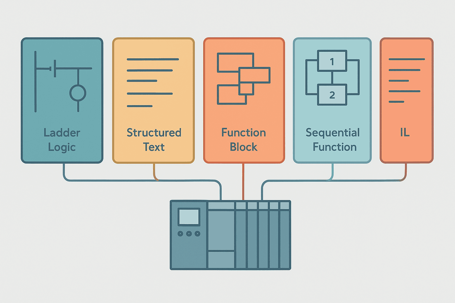
Before IEC 61131-3 was published in 1993, every PLC vendor had their own proprietary language. Siemens had STEP, Allen-Bradley had relay ladder and 6200 Series instruction sets, Modicon had Concept. If you changed brands you basically started from scratch. The standard introduced a common programming model with five languages: Ladder Diagram (LD), Structured Text (ST), Function Block Diagram (FBD), Sequential Function Chart (SFC) and Instruction List (IL). IL was officially withdrawn in the 2013 edition, but you will still find it in legacy code and some older controllers, so it is worth knowing.
Ladder Diagram (LD): The Default for a Reason
Ladder Diagram is the most widely used PLC language in North America and still dominant globally in discrete manufacturing. It was designed to look like relay logic drawings so that electricians already familiar with control schematics could read and maintain PLC code without learning to program. Two vertical rails represent power rails. Between them you draw rungs containing contacts (inputs, conditions) and coils (outputs, actions).
Ladder is genuinely excellent for discrete I/O control, interlocks, sequences with many parallel conditions, and anything where you need an electrician or maintenance tech to troubleshoot live without a laptop. The graphical online view shows you exactly which contacts are energised in real time. That alone saves hours of fault-finding on the floor. It gets unwieldy fast when you need maths, string handling, or nested logic with many variables. Anything involving floating-point arithmetic in Ladder is painful.
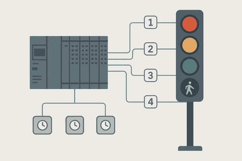
TOF Fan Purge Delay After Motor Stop (CODESYS / Generic). Ladder logic (3 rungs): Rung 0: examine if Motor_Run_Cmd is on (XIC), then energize output Motor_Output (OTE). Rung 1: examine if Motor_Run_Cmd is on (XIC), then TOF on Purge_Timer. Rung 2: examine if Purge_Timer.Q is on (XIC), then energize output Purge_Fan_Output (OTE). When Motor_Run_Cmd drops, the TOF timer holds Purge_Timer.Q TRUE for 30 seconds, keeping the purge fan running after the motor stops. The fan output de-energises automatically once the delay expires. This is a classic post-run ventilation interlock used in enclosed motor starters and paint booths.
The diagram above evaluates one scan. Run these exact rungs on a real scan cycle to watch the latching and the timers behave.
Run this in the simulatorStructured Text (ST): The Engineer's Favourite
Structured Text looks like Pascal or a simplified version of C. It uses variables, assignments, IF/THEN/ELSE, CASE statements, FOR loops, WHILE loops, and function calls. If you have ever written any high-level code, ST will feel immediately familiar. Most modern platforms use it: Siemens calls their version SCL, Beckhoff TwinCAT uses it natively in TwinCAT 3 alongside C++, and CODESYS ST is the closest thing to a universal implementation.
(* Scale a 0-27648 raw integer from a 4-20 mA input to engineering units *)
(* Raw_Count is INT, Scaled_Value is REAL *)

VAR
    Raw_Count   : INT   := 0;
    Scaled_Value: REAL  := 0.0;
    EU_Low      : REAL  := 0.0;    (* e.g. 0.0 bar *)
    EU_High     : REAL  := 10.0;   (* e.g. 10.0 bar *)
    Raw_Low     : REAL  := 0.0;    (* 0 counts = 4 mA *)
    Raw_High    : REAL  := 27648.0; (* 27648 counts = 20 mA, S7 convention *)
END_VAR

(* Linear interpolation *)
Scaled_Value := EU_Low + ((INT_TO_REAL(Raw_Count) - Raw_Low) / (Raw_High - Raw_Low)) * (EU_High - EU_Low);

(* Clamp to valid range *)
IF Scaled_Value < EU_Low THEN
    Scaled_Value := EU_Low;
ELSIF Scaled_Value > EU_High THEN
    Scaled_Value := EU_High;
END_IF;
That code would take a dozen rungs in Ladder with MOV, CPT, and comparison instructions scattered everywhere. In ST it is six meaningful lines. ST is the right choice for recipe management, PID tuning logic, protocol parsers, mathematical transformations, and any algorithm with more than a couple of branches. If you are scaling analog signals, the analog scaling calculator can verify your EU_Low and EU_High numbers before you key them into code.
The downside: an electrician on the shop floor at 2 AM cannot read it without training, and going online in ST does not give you the same visual feedback as Ladder. For anything safety-critical or where maintenance staff need to trace logic without a programmer present, Ladder still wins on accessibility.
Function Block Diagram (FBD): Signals Flowing Left to Right
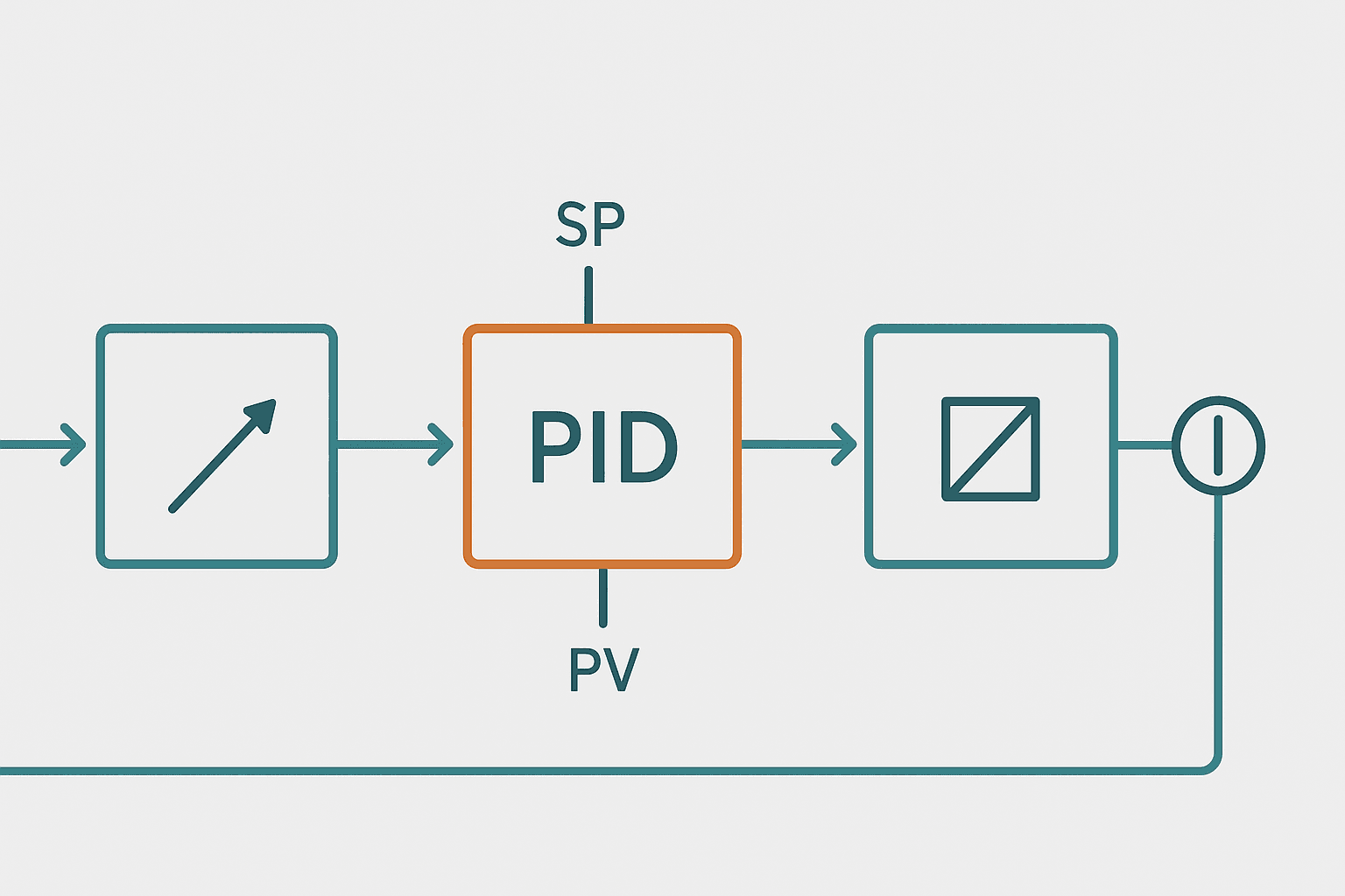
FBD represents logic as a network of interconnected function blocks, where outputs of one block feed inputs of the next. It is the natural language for process engineers who think in terms of signal flow, PID loops, and instrumentation diagrams. A PID block has inputs for setpoint, process variable, and tuning parameters, and an output for control value. You wire them together graphically. Siemens uses FBD extensively in process applications; Omron Sysmac Studio supports it well for motion profiles.
FBD shines in continuous process control: flow, temperature, pressure, level loops. It also works well for signal conditioning chains, where you might pass a raw analog value through a scaling block, then a limit alarm block, then a PID block. The graphical wiring makes the signal path obvious. It gets cluttered fast when you have complex discrete interlocks mixed in. Most engineers use FBD for the continuous parts and Ladder or ST for the discrete parts within the same project.
Sequential Function Chart (SFC): Built for State Machines
SFC is modelled after Grafcet, a French graphical specification language from the 1970s. You define steps (states) and transitions (conditions that move from one step to the next). Each step contains actions written in any of the other languages. SFC is the single best tool for multi-step sequences: filling machines, washing cycles, injection moulding cycles, test rigs, pick-and-place routines.
A typical SFC for a washing machine might have steps like: Wait For Start, Fill Tank, Heat Water, Wash, Drain, Rinse, Spin. Each transition between steps has a condition: tank_full, temp_reached, drain_empty, and so on. You can see the active step highlighted in the editor during online monitoring, which makes it very easy to identify exactly where a cycle is stuck. Siemens GRAPH and Rockwell SFC both implement this well. CODESYS SFC is particularly clean.
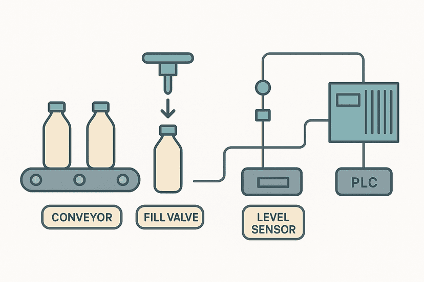
Where SFC falls down is one-shot or continuous control tasks. There is no benefit running a simple conveyor jog command through an SFC. Use it for things that have a defined start, a sequence of distinct states, and a defined end. For anything cyclical with branching paths, SFC with divergences (AND-splits and OR-splits) is hard to beat. The bottle filling project on this site shows a practical example of a multi-step sequence that maps directly to an SFC structure.
Instruction List (IL): Legacy You Cannot Ignore
IL is a low-level mnemonic language, similar to assembly. You work with a single accumulator and load values into it, then apply operations. A simple AND contact followed by a coil looks like this in IL:
LD    Motor_Enable      (* Load Motor_Enable into accumulator *)
AND   Fault_Clear       (* AND with Fault_Clear *)
ANDN  EStop_Active      (* AND NOT with EStop_Active *)
ST    Motor_Output      (* Store result to Motor_Output *)
IEC 61131-3 deprecated IL in the 2013 edition, and for good reason. It is verbose, hard to read, and provides no debugging advantages over ST. But you will encounter it in Siemens STL (Statement List), older Omron controllers using mnemonic programming, and legacy CODESYS 2.x projects. Knowing how to read it is more important than knowing how to write it. If you are maintaining an IL program and have the option to migrate, ST is almost always the better destination.
Which Language Should You Use: A Practical Guide
| Language | Best For | Avoid When | Vendor Examples |
|---|---|---|---|
| Ladder (LD) | Discrete I/O, interlocks, maintenance-readable logic | Complex maths, string handling, nested algorithms | Studio 5000, TIA Portal, GX Works, Sysmac |
| Structured Text (ST) | Algorithms, recipes, scaling, data manipulation, loops | Simple on/off logic that electricians must read | TwinCAT, CODESYS, SCL in TIA Portal, Studio 5000 |
| Function Block Diagram (FBD) | PID loops, signal conditioning, continuous process control | Complex discrete interlocks, large sequential logic | TIA Portal, Sysmac, CODESYS, Studio 5000 |
| Sequential Function Chart (SFC) | Multi-step sequences, batch processes, state machines | Continuous or simple single-rung control | TIA Portal GRAPH, Studio 5000 SFC, CODESYS |
| Instruction List (IL) | Reading legacy code only | Any new project | Siemens STL, older CODESYS 2.x |
Mixing Languages in One Project
Every modern platform lets you mix languages within a single project, and you should use that. A well-structured project might use SFC at the top level to control a filling sequence, call Ladder routines for safety interlocks and motor control, use ST functions for scaling and recipe calculations, and use FBD for PID loops. The IEC 61131-3 model calls these Program Organisation Units (POUs): programs, function blocks, and functions. They can be written in different languages and call each other freely.
In Siemens TIA Portal, a typical S7-1500 project might have an OB1 main program in LAD, a filling sequence FB in GRAPH, a PID_Compact instance in FBD, and a scaling function in SCL. In Rockwell Studio 5000, you might have a main routine in Ladder, a motion sequence routine in SFC, and a recipe handler routine in ST. This is completely normal and encouraged. Forcing everything into one language because someone made a blanket rule is how you end up with 800-rung Ladder programs full of CPT instructions trying to do what five lines of ST would do cleanly.
PLC Programming Languages and the Scan Cycle
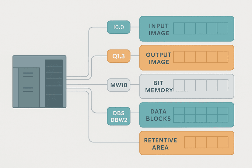
Regardless of which language you use, the PLC scan cycle works the same way: read inputs, execute program, write outputs, repeat. The language choice does not change scan behaviour. ST and FBD execute just as deterministically as Ladder. What does change is execution order within a task. In Ladder, rungs execute top to bottom, left to right. In FBD, blocks execute in the order they are wired, which the compiler resolves. In SFC, only the actions associated with the currently active step execute each scan. Understanding this matters when you have cross-language calls and shared variables. See PLC Memory and Addressing Explained for a deeper look at how the CPU handles variable updates across tasks.
Frequently asked questions
Which PLC programming language is most common?
Do all PLCs support all five IEC 61131-3 languages?
Can I use more than one programming language in a single PLC project?
What is the difference between Ladder and Structured Text in practice?
Is Instruction List (IL) still used in new PLC projects?
When should I use Sequential Function Chart instead of Ladder?
Now build it
You have just read about CPT. Reading a rung and making one behave are different skills, and the second one is the job.
Cycle Warning Window (compare)
Advancedabout 15 minA 3-second cycle should flash a warning during its FINAL second only. You can't do that with DN bits alone: you compare the timer's accumulated value against a number.
Build this rungFree, no signup, runs in your browser. See all 16 exercises.
Was this helpful?