Traffic Light PLC Exercise: Full Ladder Logic
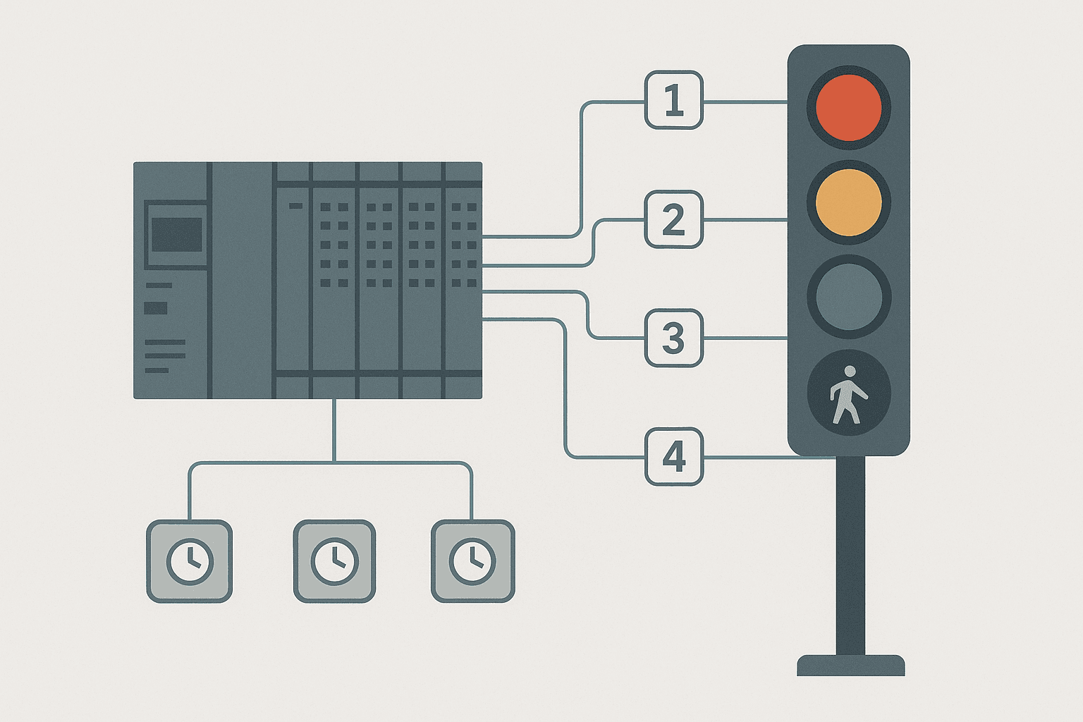
The traffic light exercise shows up in every PLC training course for a reason: it forces you to think about states, timers, and output interlocking all at once. Done properly it is not trivial. Done badly, you end up with overlapping greens and a simulation that crashes the moment you add a pedestrian button. This post builds the whole thing from scratch in Rockwell Studio 5000 ladder, walks you through the state machine logic, and finishes with a pedestrian call extension that is actually safe.
Define the Traffic Light PLC Exercise Spec
Before touching a rung, write down what the system must do. Skipping this step is why most beginner attempts end up with a timer that never resets or a green light that stays on forever.
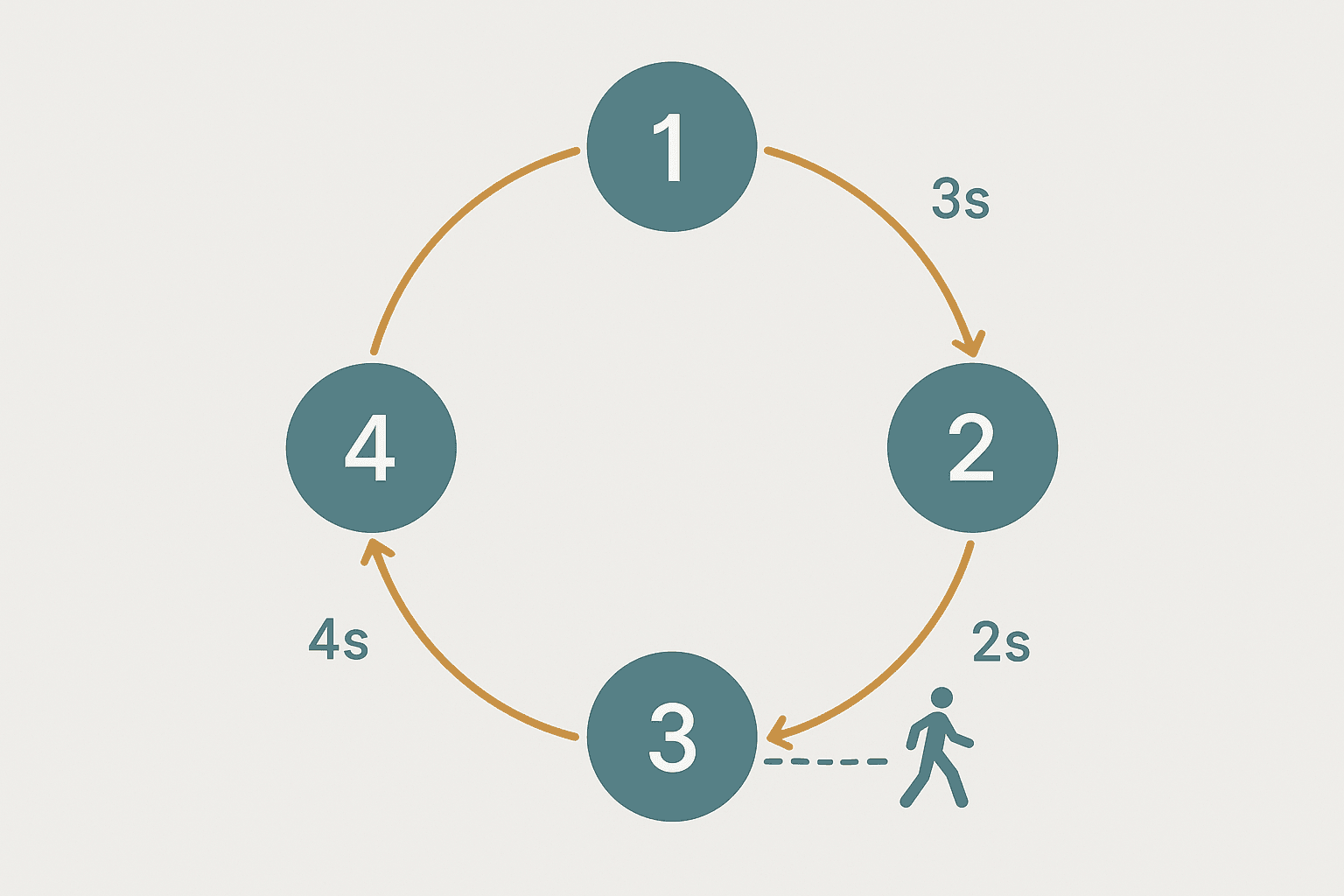
For this exercise we model a single-direction traffic signal with four phases:
| Phase | State Tag | Outputs ON | Duration (s) |
|---|---|---|---|
| 1 | State = 1 | Red | 10 |
| 2 | State = 2 | Red + Amber (prepare) | 3 |
| 3 | State = 3 | Green | 15 |
| 4 | State = 4 | Amber (clear) | 4 |
After phase 4 the state wraps back to 1. The pedestrian call button can only trigger at the end of phase 3, forcing an early amber. It cannot interrupt phase 1 or 2 because a car may already be crossing.
Tag List
| Tag Name | Type | Description |
|---|---|---|
| TL_State | INT | Current phase: 1 to 4 |
| Phase_Timer | TIMER | Single reused TON, resets on state change |
| Ped_CallBtn | BOOL | Normally-open pushbutton input |
| Ped_CallLatch | BOOL | Latched pedestrian request |
| TL_Red | BOOL | Red lamp output |
| TL_Amber | BOOL | Amber lamp output |
| TL_Green | BOOL | Green lamp output |
| TL_Walk | BOOL | Walk signal output |
| Sys_Enable | BOOL | Master enable from HMI or key switch |
State Machine Design First, Rungs Second
This is the discipline that separates engineers who build maintainable PLC code from those who build spaghetti. Draw the states and transitions on paper before you open the software. The traffic light has four states in a ring, with one conditional branch: if Ped_CallLatch is set while in state 3, the green phase cuts short as soon as the timer hits 8 seconds instead of waiting for the full 15.
Each rung group does one of three jobs: advance the state, reset the timer, or drive outputs. Keep these three jobs in separate rung groups. Mixing output coils and state-change logic in the same rung makes it almost impossible to debug later.
Ladder Rungs: State Advance Logic
The approach below uses an EQU comparison on TL_State plus the timer done bit to trigger a MOV instruction that writes the next state number. Immediately after the MOV, a RES resets Phase_Timer so it starts fresh in the new state. In Studio 5000 these are standard ladder instructions on the same rung.
// ---------------------------------------------------------------
// Rung 1: Phase 1 (Red) -> Phase 2 after 10 s
// EQU TL_State = 1, Phase_Timer.DN = 1 (10 000 ms preset)
// ---------------------------------------------------------------
[EQU(TL_State,1)][XIC(Phase_Timer.DN)] [MOV(2,TL_State)] [RES(Phase_Timer)]

// ---------------------------------------------------------------
// Rung 2: Phase 2 (Red+Amber) -> Phase 3 after 3 s
// ---------------------------------------------------------------
[EQU(TL_State,2)][XIC(Phase_Timer.DN)] [MOV(3,TL_State)] [RES(Phase_Timer)]

// ---------------------------------------------------------------
// Rung 3: Phase 3 (Green) -> Phase 4 after 15 s OR after 8 s
//         if pedestrian call is latched
// ---------------------------------------------------------------
[EQU(TL_State,3)]
  [XIC(Phase_Timer.DN)]                             [MOV(4,TL_State)] [RES(Phase_Timer)] [OTU(Ped_CallLatch)]
  [GEQ(Phase_Timer.ACC,8000)][XIC(Ped_CallLatch)]   [MOV(4,TL_State)] [RES(Phase_Timer)] [OTU(Ped_CallLatch)]

// ---------------------------------------------------------------
// Rung 4: Phase 4 (Amber clear) -> Phase 1 after 4 s
// ---------------------------------------------------------------
[EQU(TL_State,4)][XIC(Phase_Timer.DN)] [MOV(1,TL_State)] [RES(Phase_Timer)]

// ---------------------------------------------------------------
// Rung 5: Initialize - if state = 0 (first scan or power-up)
//         write 1 so the machine starts in Phase 1
// ---------------------------------------------------------------
[EQU(TL_State,0)] [MOV(1,TL_State)]
Ladder Rungs: Timer and Output Rungs
The timer rung runs every scan when Sys_Enable is on. The preset changes depending on the current state. In Studio 5000 you can use a MOV to write the preset into Phase_Timer.PRE before the TON rung, or just hard-code separate TON instructions gated by the state comparison. The separate-TON approach is more readable for training purposes.
// ---------------------------------------------------------------
// Timer rungs: one TON per phase, only the active one accumulates
// ---------------------------------------------------------------
[XIC(Sys_Enable)][EQU(TL_State,1)]  TON(Phase_Timer, 10000, 0)  // 10 s Red
[XIC(Sys_Enable)][EQU(TL_State,2)]  TON(Phase_Timer,  3000, 0)  //  3 s Red+Amber
[XIC(Sys_Enable)][EQU(TL_State,3)]  TON(Phase_Timer, 15000, 0)  // 15 s Green
[XIC(Sys_Enable)][EQU(TL_State,4)]  TON(Phase_Timer,  4000, 0)  //  4 s Amber

// ---------------------------------------------------------------
// Output rungs: assign lamps to states
// Red ON in states 1 and 2
// ---------------------------------------------------------------
[XIC(Sys_Enable)][[EQU(TL_State,1)],[EQU(TL_State,2)]]  OTE(TL_Red)

// Amber ON in states 2 and 4
[XIC(Sys_Enable)][[EQU(TL_State,2)],[EQU(TL_State,4)]]  OTE(TL_Amber)

// Green ON in state 3 only
[XIC(Sys_Enable)][EQU(TL_State,3)]  OTE(TL_Green)

// Walk signal ON in state 1 (pedestrians cross while vehicles wait)
[XIC(Sys_Enable)][EQU(TL_State,1)]  OTE(TL_Walk)

// ---------------------------------------------------------------
// Pedestrian call latch
// ---------------------------------------------------------------
[XIC(Ped_CallBtn)] OTL(Ped_CallLatch)TL_Green and TL_Red can never both be ON because they are gated by mutually exclusive state values. If you ever see both lamps on simultaneously during commissioning, your state variable has gone corrupt (usually a runaway MOV or an uninitialised tag). Force TL_State to 0 and let the initialisation rung reset it to 1.Interactive Ladder: Pedestrian Call and Walk Signal
The rung below shows the pedestrian call latch together with a one-shot that clears it only when the walk signal actually activates in phase 1. This prevents a phantom second latch from a button press that happened during phase 2 or 4.
Traffic Light: Pedestrian Call Latch and Walk Activation (Studio 5000). Ladder logic (3 rungs): Rung 0: examine if Ped_CallBtn is on (XIC), then examine if Ped_CallLatch is off (XIO), then latch output Ped_CallLatch (OTL). Rung 1: examine if TL_Walk is on (XIC), then examine if Walk_Rise_OS is on (XIC), then unlatch output Ped_CallLatch (OTU). Rung 2: examine if Sys_Enable is on (XIC), then examine if TL_Walk is on (XIC), then energize output Walk_Lamp_Out (OTE). Rung 1: Latches the pedestrian call on the first button press; the XIO contact prevents re-latching while already active. Rung 2: A rising-edge one-shot on the Walk output clears the latch the moment phase 1 starts and the walk lamp turns on, so the next press is a fresh request. Rung 3: Drives the physical walk lamp output only when the system is enabled.
The diagram above evaluates one scan. Run these exact rungs on a real scan cycle to watch the latching and the timers behave.
Run this in the simulatorCommon Mistakes in the Traffic Light PLC Exercise
- Not initialising the state tag. A BOOL or INT tag in Studio 5000 defaults to 0 on first scan. Without the initialisation rung the timer never runs because no state rung is active.
- Forgetting to RES the timer. If you just write a new state value but leave the accumulated value in the timer, the new phase may complete instantly because the .DN bit is already set.
- Separate coils for the same output. If you put TL_Red as an OTE on two different rungs, only the last rung evaluated wins (last-rung-wins scan rule). Use parallel branches on a single rung instead.
- Pedestrian button wired as normally closed. A stuck-on walk request will force green to cut short every cycle. Wire the input as normally open and confirm it with a multimeter before download.
- Overlapping output assignments. Assigning Amber to states 2, 3, and 4 by accident is easy when copying rungs. A quick cross-reference check in Studio 5000 (Ctrl+G on the tag) catches this in seconds.
How to Simulate It Without Physical Hardware
Studio 5000 Logix Designer includes the built-in emulator (Logix Emulate 5000) that runs the exact same scan engine as a real ControlLogix or CompactLogix. Download the program to the emulated controller, go online, and watch TL_State tick through 1, 2, 3, 4 in the tag monitor. Force Ped_CallBtn to 1 while the state is 3 and watch the phase cut short at 8 seconds.
If you are using CODESYS, the built-in simulator under PLC > Simulation works identically. Map the outputs to visualisation elements (a simple rectangle with a fill colour tied to the BOOL tag) and you get a working animated traffic light on screen without spending a penny on hardware.
For TIA Portal users the S7-PLCSIM advanced v4 or later supports the same timer instruction set. The project transfers without modification because the TON instruction and EQU comparison behave identically in IEC 61131-3 compliant platforms.
Extension Challenges to Push Your Skills
Once the basic cycle runs cleanly, try these extensions in order of difficulty:
- Add a night-flash mode. When a
Night_Modebit is set, all state logic pauses and Amber flashes at 1 Hz using a TON/TOF pair. Returning to day mode should always restart in phase 1. - Add a fault output. If
TL_Statesomehow lands on a value outside 1 to 4 (a diagnostic sanity check), latch aTL_FaultAlarmbit and turn all lamps off. This is a real-world requirement on most traffic controller specs. - Build the second direction. Model a crossing junction with a second signal on outputs TL2_Red, TL2_Amber, TL2_Green. The two signals must be interlocked: TL2_Green can only be ON when TL_State = 1 (first direction is red).
- Add a vehicle sensor input. A loop detector input (simulated by a pushbutton in the lab) can extend the green phase by 5 seconds, up to a maximum of 30 seconds, using a GEQ comparison on the accumulated value.
- HMI faceplate. Build a simple TIA Portal or FactoryTalk View SE screen with coloured indicator lamps tied to the output tags, a phase timer bar graph, and a manual override button. This ties together the exercise with real HMI work.
Why This Exercise Matters Beyond the Traffic Light
The same integer-state pattern used here scales directly to real industrial sequencers: a wash cycle with soak, rinse, and spin phases; a conveyor indexer with load, index, and unload steps; an oven profile with ramp, soak, and cool stages. Every one of those is a traffic light in disguise. Get comfortable with the EQU-MOV-RES pattern and the timer-per-state approach, and you will find sequencer logic much less intimidating on your next actual project.
For a more complex sequencer that uses the same principles on a real production machine, see the PLC Bottle Filling Machine project, which chains five states with conditional branching based on both timers and sensor inputs.
Frequently asked questions
What outputs do I need for a traffic light PLC exercise?
Why use a state integer instead of separate timer rungs for each colour?
How do I prevent the timer from missing a reset in ladder logic?
Can I do this exercise in structured text instead of ladder?
How do I stop both green lights being on at the same time in a two-direction junction?
Is the traffic light exercise realistic for industrial PLC training?
Now build it
You have just read about MOV and EQU. Reading a rung and making one behave are different skills, and the second one is the job.
Mode (Auto / Manual)
Intermediateabout 15 minTwo mutually exclusive mode coils selected by momentary buttons: the skeleton behind every Auto/Manual selector. Each mode seals itself in, and pressing the other button switches over cleanly.
Build this rungFree, no signup, runs in your browser. See all 16 exercises.
Was this helpful?