
📢 Fresh Content: PLC Troubleshooting Tips That Work Across Any Platform | Click to read on PLCDocs!
Topic hub
Electrical and Panels
Control panel design and the electrical fundamentals behind it: overcurrent protection, transformers and 24 V supplies, contactors and starters, wire routing, segregation and grounding.
A PLC program is only as reliable as the panel around it. Most of the faults that look like software are a shared neutral, an undersized supply, a shield grounded at both ends, or a control transformer chosen on steady-state current with no allowance for contactor inrush. This is the hardware side of controls work.
11 articles in this hub
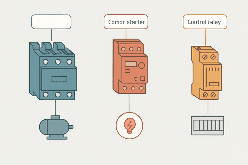
Contactor vs Motor Starter vs Relay: Key Differences
Contactors, motor starters and control relays are often confused but serve distinct roles. This guide breaks down ratings, construction and when to use each one in a control panel.
Aug 9, 2026 · 8 min read
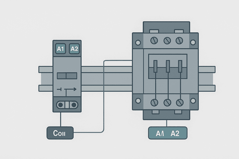
Relay vs Contactor: Wiring Differences Explained
Relays and contactors both switch circuits, but they're built for different jobs. Learn the key wiring differences, coil ratings, auxiliary contacts, and when each device belongs in your panel.
Jul 24, 2026 · 9 min read
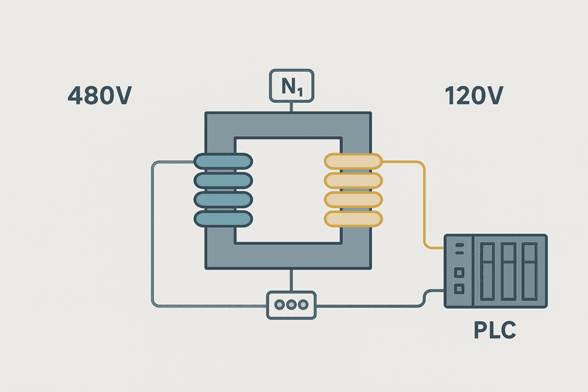
Electrical Transformer Basics: How They Work and How to Wire Them
Learn how electrical transformers work, how to calculate turns ratio and VA sizing, and how to wire a 24V control transformer step by step.
Jul 24, 2026 · 9 min read
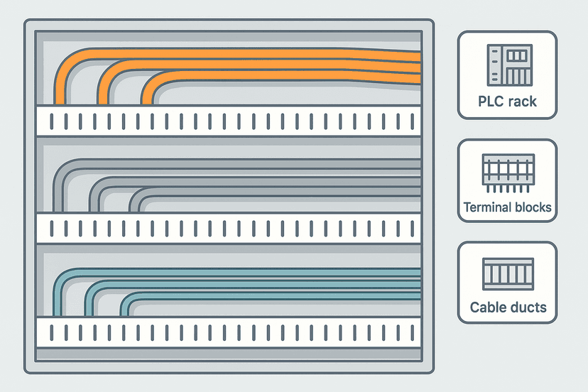
Control Panel Wire Routing and Segregation
Mixing power and signal wires in a control panel causes noise, spurious faults and headaches. Here is how to route and segregate them correctly.
Jul 13, 2026 · 8 min read
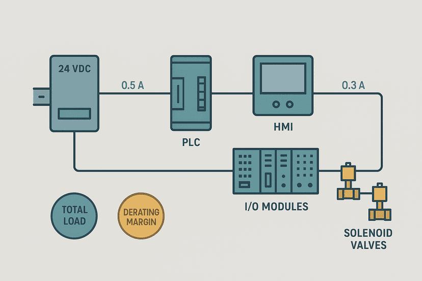
24 VDC Power Supply Sizing for Control Panels
Learn how to size a 24 VDC power supply for a PLC control panel: load tallying, derating, inrush, redundancy options and real worked examples.
Jul 13, 2026 · 10 min read
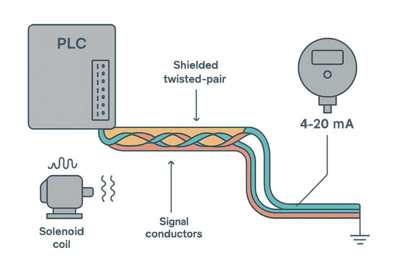
Shielding Analog Signal Cables in PLC Panels
Analog noise in PLC panels usually traces back to wrong shield grounding. Here's the exact technique, the common mistakes and the real-world numbers that matter.
Jul 12, 2026 · 8 min read
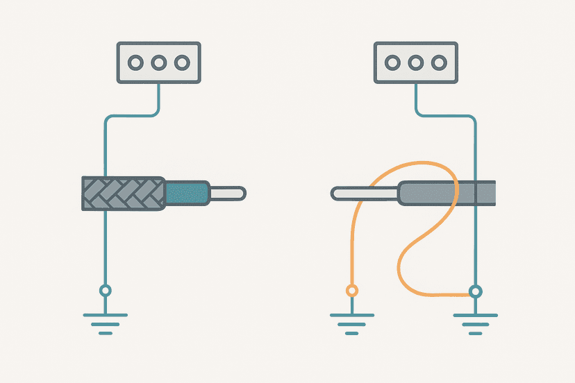
Cable Shield Grounding: One End or Both?
Shield grounding is one of the most argued topics in panel design. Here is the engineering behind single-point vs both-end termination, with real rules for 4-20 mA, thermocouples and fieldbus.
Jul 12, 2026 · 8 min read
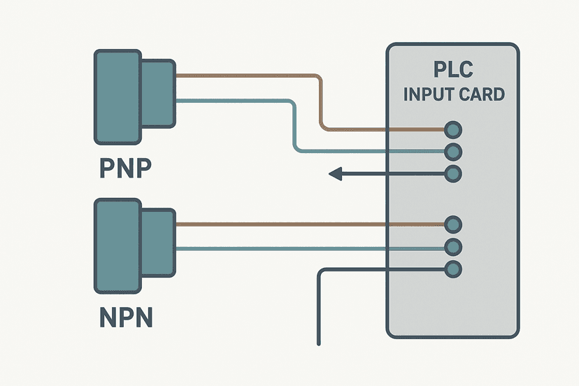
3-Wire Sensor Wiring: PNP vs NPN to PLC Inputs
PNP or NPN sensor, sinking or sourcing input? Learn exactly how to wire 3-wire sensors to any PLC input card with real wiring rules and common mistakes.
Jul 1, 2026 · 9 min read
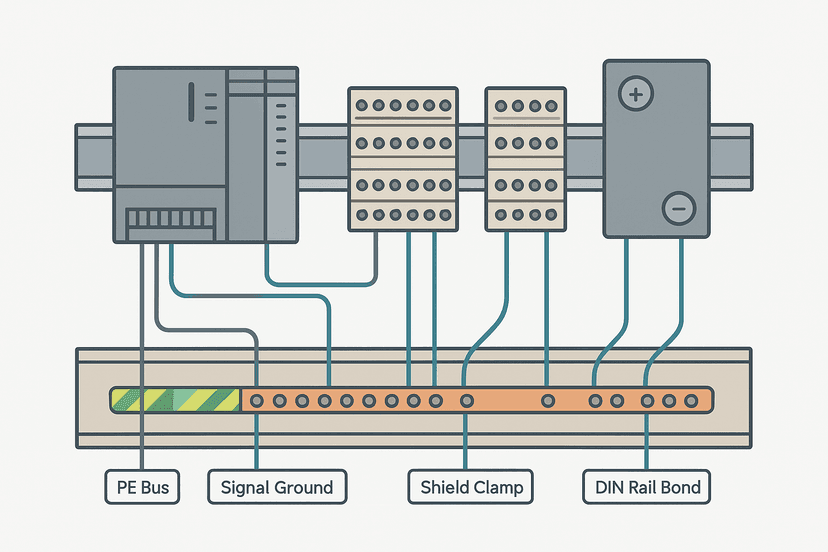
Control Panel Grounding: The Right Way to Do It
Bad grounding is the number-one silent killer of PLC panels. Learn the correct techniques for PE, signal ground, and shield termination in industrial control panels.
Jun 30, 2026 · 9 min read
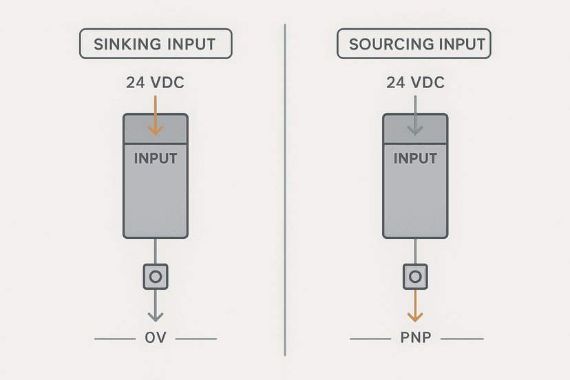
Sinking vs Sourcing PLC I/O: Wiring It Right
Sinking vs sourcing PLC I/O confuses almost every technician at least once. Here is the current-flow logic that makes it click, plus real wiring rules.
Jun 30, 2026 · 8 min read
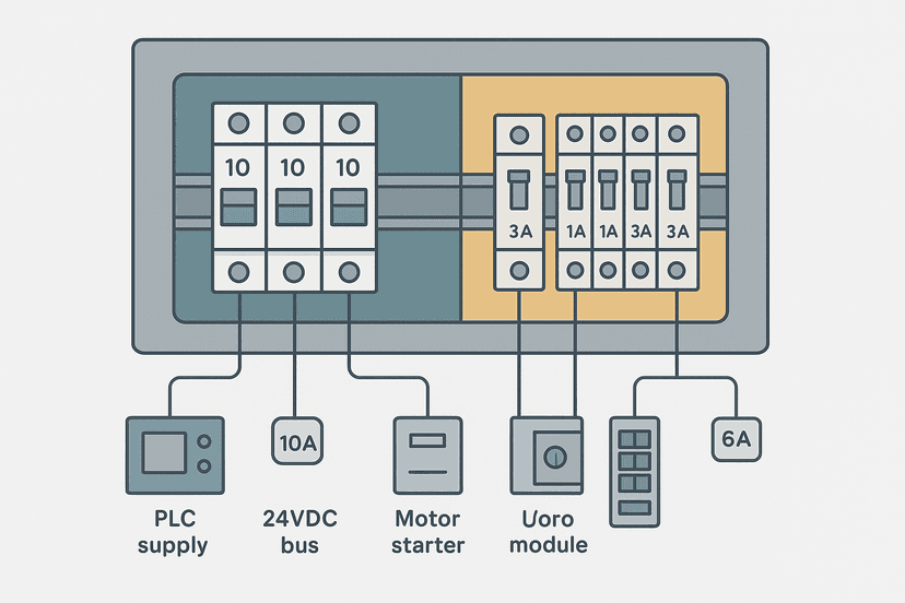
Fuse vs Breaker Selection for Control Panels
Choosing between fuses and breakers for a control panel isn't just about amps. Learn how to match devices to fault current, load type, and coordination requirements.
Jun 27, 2026 · 7 min read