Relay vs Contactor: Wiring Differences Explained
Walk past any control panel and you'll see both relays and contactors on the DIN rail. They share the same basic idea: a coil energizes, contacts close, a load gets power. But wire them up the same way and you'll have burned contacts, nuisance trips, or a PLC output card that lasts six months instead of ten years. The two devices are built for completely different jobs, and the wiring rules that go with each one reflect that.
What Is the Difference Between a Relay and a Contactor?
A control relay is a low-power switching device with contacts typically rated 5 A to 10 A, used to route signals inside a control circuit. A contactor is a heavy-duty switching device built to make and break high-current load circuits repeatedly, starting at around 9 A and going up to hundreds of amps. Contactors carry arc suppression features, heavier silver-alloy contacts, and a mechanical structure designed to survive the inrush currents of motors and capacitor banks.
Construction: Why Size and Materials Matter
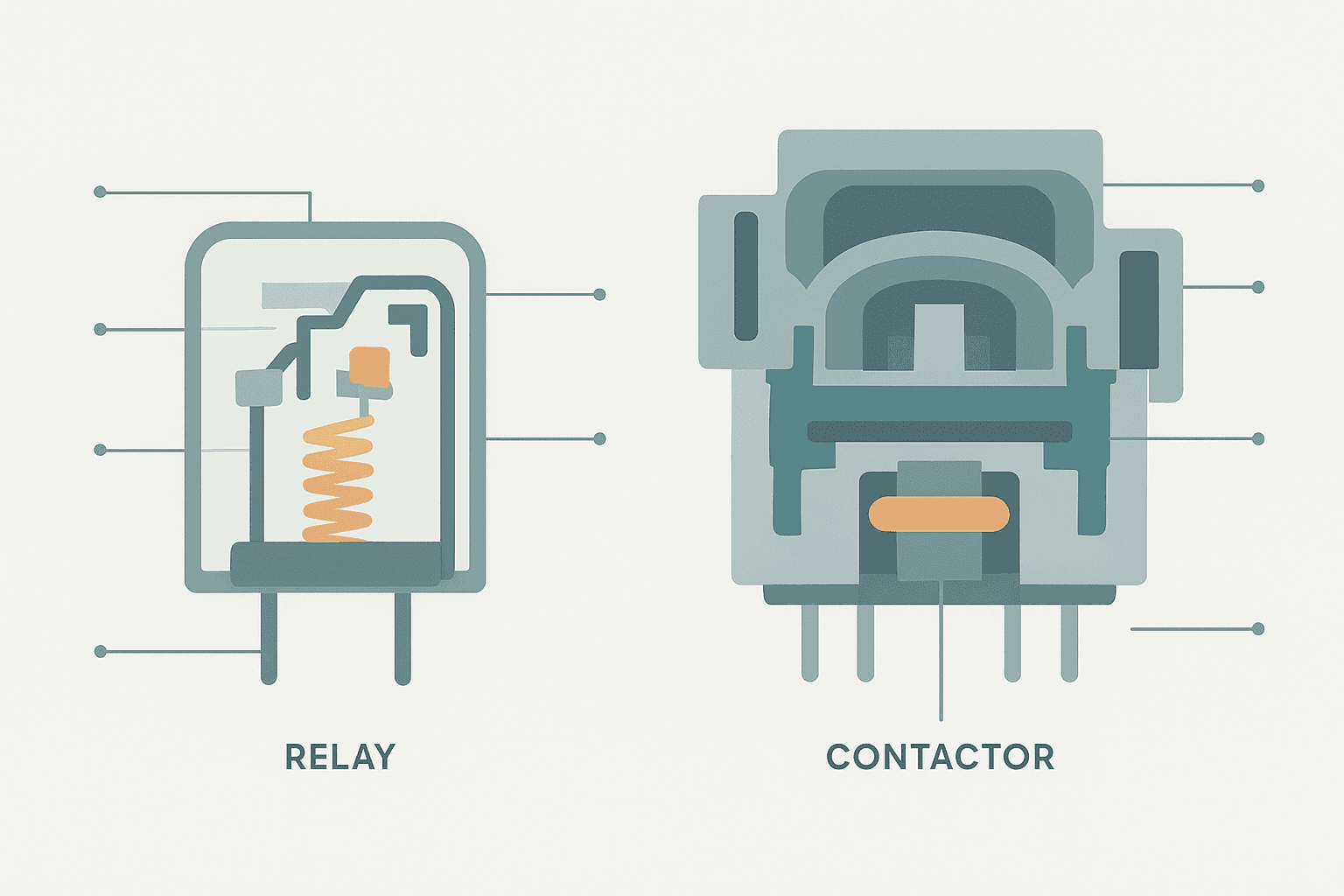
A standard DIN-rail relay, like a Phoenix Contact PLC-RSC or an Omron MY4, uses silver-cadmium oxide or silver-nickel contacts in a compact plastic housing. The contact gap is small because the currents are small. Breaking a 5 A resistive load at 24 VDC produces a manageable arc.
A contactor (think Schneider TeSys D, Siemens 3RT, or Eaton DILM series) uses much larger silver-alloy contacts, a blow-out chamber to extinguish arcs, and a laminated iron core with a shading ring to prevent 50/60 Hz buzzing on AC coils. The main contacts are rated by IEC 60947-4-1 utilization categories. For motor switching the relevant category is AC-3. For resistive loads it's AC-1. Never pick a contactor frame size based on AC-1 current if you're running a motor.
Coil Wiring: A1, A2 and Voltage Selection
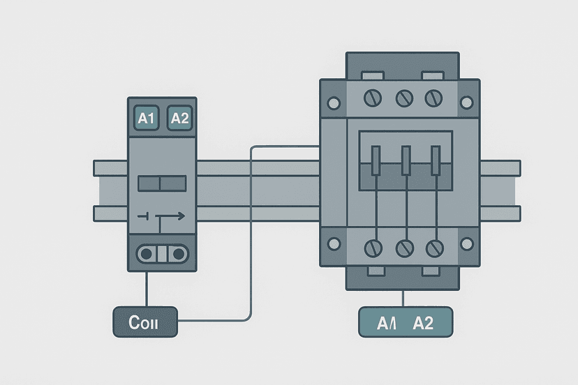
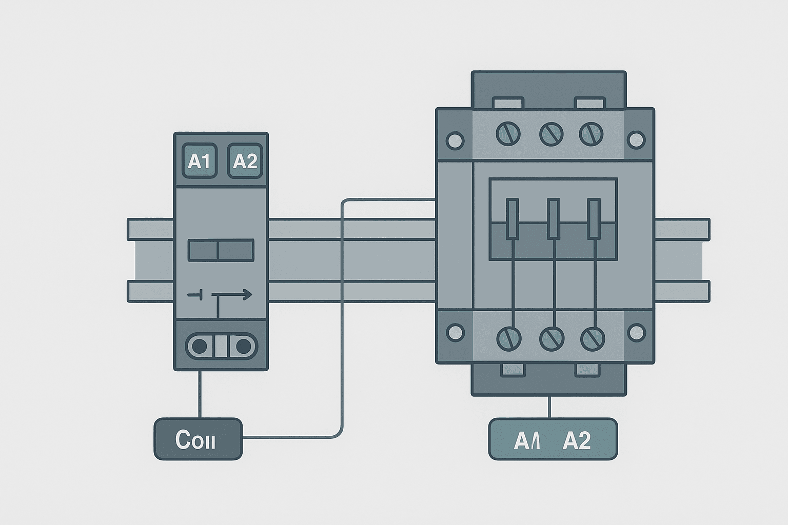
Both devices use A1 and A2 as coil terminals. The convention is the same: apply your control voltage across A1 (+) and A2 (-) for DC coils, or across A1 (live) and A2 (neutral) for AC coils. The similarity ends there.
Most modern panels use 24 VDC control circuits because PLC output cards drive 24 VDC directly and the 24 VDC power supply sizing is straightforward. Choose a 24 VDC coil contactor and you can drive it straight from a PLC transistor output. The coil inrush on a Schneider LC1D09 24 VDC contactor is around 70 mA steady-state with a short inrush spike, well within the 0.5 A limit of most transistor output cards.
If you're driving an AC coil contactor (120 VAC or 230 VAC) from a PLC relay output, check the relay output's AC current rating. A PLC relay output is typically rated 2 A at 240 VAC for resistive loads but derated for inductive loads. An AC contactor coil is inductive, so verify the output module's inductive rating in the datasheet. Fitting a fuse or breaker in the coil circuit protects the output card if a coil shorts.
Coil Suppression: Relays and Contactors Both Need It
When a coil de-energizes, the collapsing magnetic field generates a voltage spike. On a 24 VDC circuit this can reach 100 V to 200 V for a fraction of a millisecond. That's enough to damage a transistor output stage over time.
- DC coil (relay or contactor): fit a flyback diode (e.g. 1N4007) across the coil, cathode to A1 (positive). Many devices have one built in. If yours doesn't, wire it externally at the terminal block.
- AC coil contactor: fit a varistor (MOV) or an RC snubber across the coil. Schneider and Siemens sell plug-in suppressor modules that snap onto the contactor body.
- PLC transistor output to DC relay: always use a relay socket with a built-in suppression LED or diode. Phoenix Contact PLC-RSC sockets include this as standard.
Main Contact Wiring: Three-Phase Contactor Layout
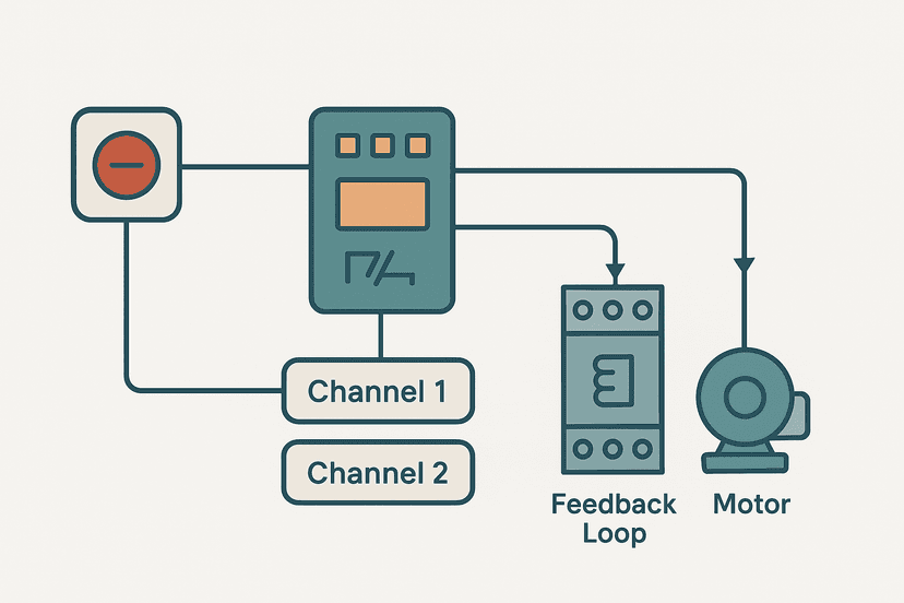
A three-phase contactor has six main contact terminals: L1, L2, L3 on the line (supply) side and T1, T2, T3 on the load (motor) side. The three phases enter from the top, pass through the contact bridge, and exit to the motor at the bottom. Between the contactor and the motor you'll almost always find a thermal overload relay. The overload relay's NC contact feeds back into the coil circuit so an overcurrent trips the coil automatically.
| Terminal | Function | Connects to |
|---|---|---|
| L1, L2, L3 | Line (supply) input | Upstream fuse or breaker output |
| T1, T2, T3 | Load output | Overload relay input (then to motor) |
| A1 | Coil positive / line | PLC output or control switch |
| A2 | Coil negative / neutral | Control circuit 0 V or neutral |
| 13/14 | Auxiliary NO contact | PLC feedback input, seal-in, or interlock |
| 21/22 | Auxiliary NC contact | Interlock or fault signal |
The terminal numbering follows IEC 60947-4-1. Main contacts use L/T prefixes. Auxiliary contacts use a two-digit number: the first digit is the contact position number and the second digit indicates function (3/4 = NO, 1/2 = NC). So 13/14 is the first auxiliary NO contact, and 21/22 is the second auxiliary contact, wired NC.
Auxiliary Contacts: Feedback, Interlocks and Seal-In
This is where contactor wiring gets more interesting from a PLC perspective. The main contacts handle motor current. The auxiliary contacts handle control current, and they're what your PLC actually talks to.
A standard IEC contactor comes with one or two auxiliary contacts on the body. You can add more by snapping on an auxiliary contact block. Common uses:
- Run feedback to PLC input: wire a NO auxiliary contact (13/14) to a 24 VDC PLC digital input. When the contactor closes, the PLC confirms the motor is energized. This is not the same as a motor running confirmation (use a current sensor or drive feedback for that), but it confirms the contactor picked up.
- Electrical interlock between two contactors (forward/reverse): wire an NC auxiliary contact from Contactor 1 in series with the coil circuit of Contactor 2, and vice versa. This is a hard-wired interlock that prevents both contactors energizing simultaneously, even if PLC logic fails. Always do this in hardware for reversing starters.
- Seal-in circuit for pushbutton start: wire the NO auxiliary in parallel with the start pushbutton so the contactor holds itself in after the operator releases the button. Less common now that PLCs handle this in software, but still seen on standalone motor starters.
For the PLC feedback use, remember that sinking vs sourcing I/O wiring determines how you route the 24 VDC through the auxiliary contact to the input card. Get this backwards and the input never sees a signal.
relay vs contactor Wiring: A Side-by-Side Comparison
| Feature | Control Relay | Contactor |
|---|---|---|
| Typical contact rating | 5 A to 10 A, 250 VAC | 9 A to 800+ A, 690 VAC |
| Main use | Control circuit switching | Load circuit switching (motors, heaters) |
| Coil voltage options | 5 V, 12 V, 24 VDC, 120/230 VAC | 24 VDC, 48 VDC, 110/120/230 VAC |
| Arc suppression | Minimal or none | Arc chamber, blow-out magnets |
| Auxiliary contacts | All contacts are auxiliary-scale | Separate add-on auxiliary contact blocks |
| Overload protection | Not included | Paired with overload relay for motor duty |
From the Field: When the Wrong Device Costs You
I commissioned a small conveyor system once where a previous integrator had used standard DIN-rail relays to switch three 0.37 kW single-phase motors directly. No contactors, no overload relays. The relay contacts were visibly pitted after about four months of three-shift operation. The inrush current on motor start was hammering the contacts on every cycle. Swapping in proper AC-3 contactors with overload relays fixed the issue and cost less than half the price of the relay failures over that same period.
The reverse mistake happens too: using a 32 A contactor to switch a 24 VDC signal because it was on the shelf. A contactor's contact materials and gap geometry are optimized for AC load currents. Switching a dry 24 VDC signal through a contactor can cause contact sticking because the arc energy at low DC voltage isn't enough to clean the contacts. Use a proper control relay for control-circuit switching.
Wiring a Contactor to a PLC Output: The Complete Path
Here's the complete wiring path for a typical three-phase motor starter controlled by a PLC:
- Three-phase supply through a motor circuit breaker (MCB) to contactor L1, L2, L3.
- Contactor T1, T2, T3 to overload relay input terminals.
- Overload relay output terminals to motor terminal box.
- 24 VDC control supply positive through the overload relay NC contact, through any interlock NC contacts, to contactor A1.
- Contactor A2 to 24 VDC common (0 V).
- PLC digital output switched in series with the A1 coil circuit (or drives a relay that does the same).
- Contactor auxiliary NO contact (13/14) wired to a PLC digital input as run confirmation.
- Overload relay trip contact wired to a separate PLC digital input as fault feedback.
For the control wiring, follow the same control panel wire routing and segregation rules you'd use for any other panel: keep 24 VDC control wiring away from power cables, use ferrules on every wire end, and label both ends. When commissioning, always verify the overload relay is set to the motor's full-load current before energizing. This is the step people skip and then wonder why the motor trips on the first start.
If the motor is being controlled by a VFD rather than a direct-on-line contactor, the contactor sits on the input side of the drive as an isolation device, not as the run/stop control. The drive handles speed and direction. Check the VFD parameters for the correct control terminal wiring once the power side is confirmed.
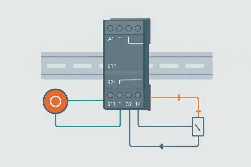
For safety-critical stopping, the coil circuit interlock might not be enough on its own. Review emergency stop circuit wiring categories to understand when a safety relay or safety PLC needs to be in the loop. If the application involves ISO 13849 or IEC 62061 requirements, the contactor auxiliary contacts contribute to the diagnostic coverage calculation. See the IEC 62061 SIL levels guide for context.
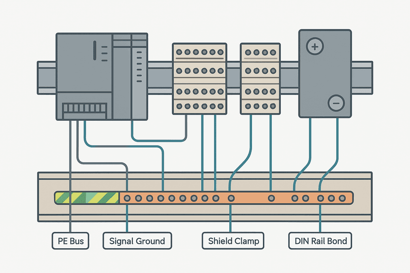
Ground your panel correctly too. A floating control circuit or a poor PE connection on the contactor frame will cause noise on PLC inputs connected to the auxiliary contacts, especially on long cable runs. The control panel grounding guide covers the right approach for the PE bonding path.
Keep Learning
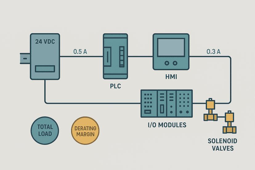
Now that you have the relay vs contactor wiring picture clear, the next step is understanding how the PLC output side works so you pick the right output module type for coil driving. Start with sinking vs sourcing PLC I/O to get that right, then look at safety relay wiring circuits to see how a dedicated safety relay fits into a stop category application. For the power supply sizing that feeds your control circuit, 24 VDC power supply sizing for control panels gives you the calculation method with real numbers.
Frequently asked questions
What is the main difference between a relay and a contactor?
Can you use a relay instead of a contactor to control a motor?
What do A1 and A2 terminals mean on a contactor or relay?
What is an auxiliary contact on a contactor and how is it wired?
What coil voltage should I choose for a contactor in a PLC panel?
Why does a contactor buzz or chatter?
Do I need a suppressor across a contactor coil?
What is AC-3 utilization category on a contactor?
How do I wire a three-phase contactor for a motor?
Now build it
You have just read about MOV. Reading a rung and making one behave are different skills, and the second one is the job.
Mode (Auto / Manual)
Intermediateabout 15 minTwo mutually exclusive mode coils selected by momentary buttons: the skeleton behind every Auto/Manual selector. Each mode seals itself in, and pressing the other button switches over cleanly.
Build this rungFree, no signup, runs in your browser. See all 16 exercises.
Was this helpful?