VFD Parameters Explained: 12 Settings You Must Get Right
Getting a VFD running in hand mode for a bench test is easy. Getting it running reliably in a real application, without nuisance trips, motor damage, or a 2 AM callout, comes down to understanding the parameters. Most drives ship with defaults that are not matched to your motor or your load. You have to set them deliberately.
What Are VFD Parameters?
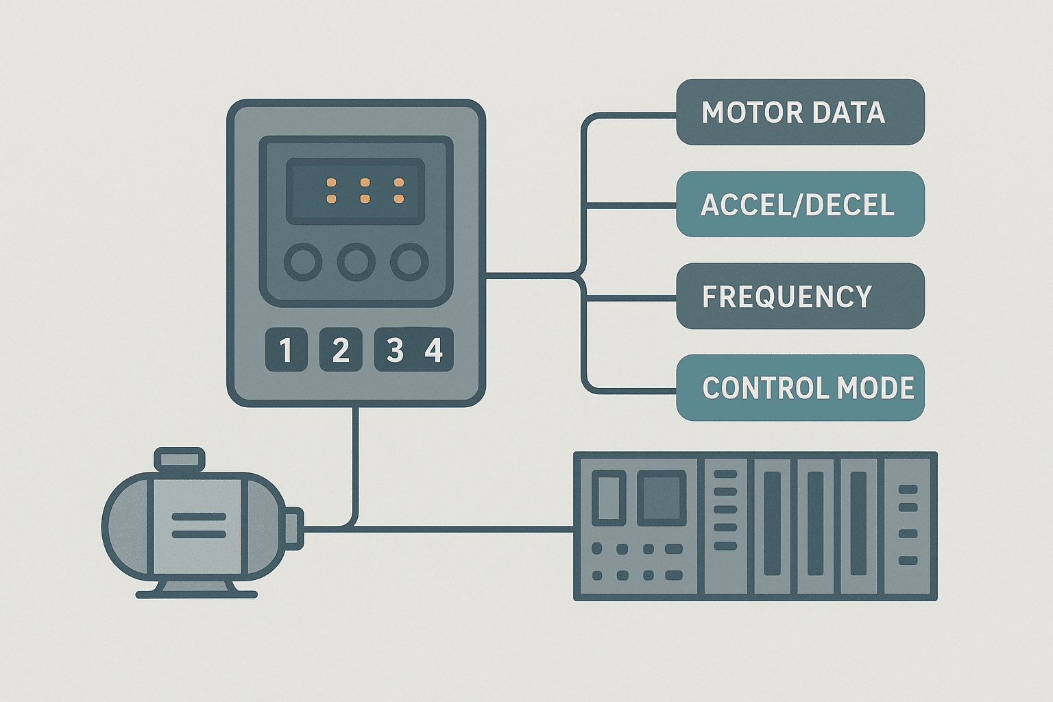
VFD parameters are the configurable settings stored in a variable frequency drive's non-volatile memory that control how the drive starts, stops, accelerates, limits current, responds to a speed reference signal, and protects the motor. They are organized into groups (motor data, control, protection, comms) and accessed via a keypad, PC software, or a fieldbus write from a PLC. Setting them correctly is the single most important commissioning task for any drive installation.
Group 1: Motor Nameplate Parameters (Set These First)
Every VFD has a set of parameters that represent the motor it is driving. These are not optional. If you skip them, the drive's overload protection, vector calculations, and slip compensation are all working from wrong numbers.
| Parameter | What to Enter | Where to Find It |
|---|---|---|
| Motor rated voltage | Nameplate voltage (e.g. 400 V) | Motor nameplate |
| Motor rated current (FLA) | Full-load amps, not drive rating | Motor nameplate |
| Motor rated frequency | 50 Hz or 60 Hz | Motor nameplate |
| Motor rated speed (RPM) | Synchronous or nameplate RPM | Motor nameplate |
| Motor rated power (kW or HP) | Nameplate kW or HP | Motor nameplate |
| Motor power factor (cos phi) | Nameplate PF if required | Motor nameplate |
Group 2: Frequency Limits
Maximum output frequency is usually 50 or 60 Hz to match the motor's design speed. You can go higher on some applications (spindles, special motors rated for it) but you need to confirm the motor's mechanical and electrical rating allows it. Do not just raise this to 70 Hz because the machine seems slow.
Minimum output frequency protects self-cooled (TEFC) motors from overheating at low speed and prevents pumps from running below the point where they generate useful flow. A setting of 20 to 25 Hz is common for HVAC fans and centrifugal pumps. For conveyors or applications that need to hold zero speed, 0 Hz is correct but you may need external cooling on the motor.
Group 3: Acceleration and Deceleration Times
Accel time is defined as the time to ramp from 0 Hz to maximum frequency. Decel time is the reverse. These are the parameters new engineers set wrong most often, and the result is an overcurrent or overvoltage trip every time the drive starts or stops.
For high-inertia loads like fans, set accel time long enough that the motor current stays below the overload threshold during the ramp. On a 55 kW supply fan, 30 seconds is not unusual. For decel on the same fan, the load tends to coast faster than the drive wants to slow it, which pumps energy back into the DC bus and causes an overvoltage trip. Either extend decel time (60 seconds or more), or fit a braking resistor or enable a built-in DC injection brake.
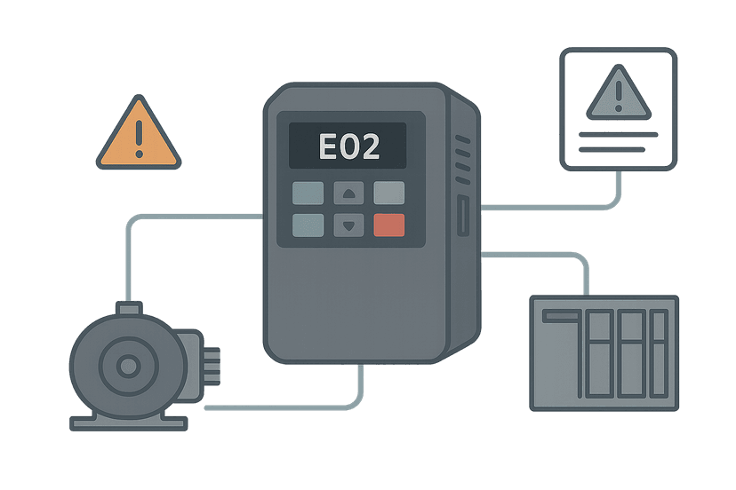
On a commissioning job at a water treatment plant a few years ago, a 37 kW blower kept tripping F0001 (overcurrent) on every start. The accel time was at the factory default of 5 seconds. Bumping it to 25 seconds and the fault never came back. That is the kind of thing that takes 30 seconds to fix once you know what to look for. If you are chasing fault codes, see the VFD Fault Codes guide for a systematic approach.
Group 4: Control Mode (V/Hz vs Vector)
The control mode parameter is one of the most consequential settings on the drive. Get it wrong and you either waste the drive's capability or make the motor unstable.
- V/Hz (Scalar): Voltage and frequency ramp together at a fixed ratio. Simple, stable, good for fans, pumps, and conveyors where precise speed or torque at low speed is not needed. This is the right default for most general-purpose work.
- Sensorless Vector (SVC/FOC without encoder): The drive estimates motor flux from current and voltage measurements. Better torque at low speed and tighter speed regulation. Requires you to run an auto-tune routine with the motor connected. Good for machine tool axes, mixers, and extruders.
- Closed-Loop Vector (with encoder): Adds a real encoder for precise speed feedback. Use this for hoists, winders, and positioning applications. Requires an encoder feedback card fitted to the drive.
- PM Motor Control: Permanent magnet motor mode for PMSM and synchronous reluctance motors. Many modern energy-efficient motors need this mode selected or the drive cannot control them correctly.
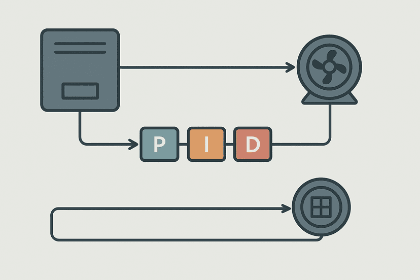
If you select vector mode, always run the auto-tune (sometimes called motor identification or auto-commissioning) with the motor at standstill or uncoupled from the load. This lets the drive measure stator resistance and leakage inductance directly. Skipping it and just entering nameplate data is fine for V/Hz but leaves vector performance on the table. Compare this to the detailed tuning work needed for servo drive PID gains, which follows a similar philosophy of measurement before tuning.
Group 5: Reference Source and Command Source
Two parameters that confuse a lot of people because they look similar but control completely different things:
- Frequency reference source: Where the speed setpoint comes from. Options are typically keypad, analog input 1 (AI1, usually 0-10 V), analog input 2 (AI2, usually 4-20 mA), preset speeds, or fieldbus (Modbus, PROFINET, EtherNet/IP).
- Run/stop command source: What triggers the drive to start and stop. Keypad RUN key, digital input terminal, or fieldbus control word.
When the PLC sends a speed reference as a 4-20 mA analog signal, set the frequency reference source to AI2 (or whichever terminal the signal lands on), and configure the input scaling so 4 mA maps to 0 Hz and 20 mA maps to maximum frequency. For the analog scaling math on the PLC side, the 4-20 mA scaling formula guide and the analog scaling calculator will save you time. Also check your PLC analog input wiring is correct before assuming the drive parameter is wrong.
For fieldbus control from a PLC over EtherNet/IP or PROFINET, both the reference source and command source point to the network. The PLC writes a speed reference word and a control word each scan cycle. If communication drops, the drive needs a defined fallback behavior set in its comms loss parameter. See EtherNet/IP scanner and adapter concepts and PROFINET IO controller/device setup for the network side of this.
Group 6: Motor Protection Parameters
Beyond motor rated current, several protection parameters deserve attention:
- Electronic thermal overload (ETH / I2t): Set the motor class (standard, heavy-duty) and the rated current. The drive models heating over time and trips before the motor windings are damaged.
- Motor thermistor input: If the motor has a PTC thermistor in the windings, wire it to the drive's thermistor input and enable the parameter. This is direct winding protection, much faster than ETH for blocked or locked rotor conditions.
- Overcurrent trip level: Usually expressed as a percentage of drive rated current (e.g. 150% for 60 seconds). Leave at default unless the application genuinely needs a different value.
- Stall prevention / current limit: Limits output current during acceleration. The drive extends accel time automatically rather than tripping. Useful for variable loads but can mask a real mechanical problem.
Group 7: Carrier Frequency
Carrier frequency (also called switching frequency or PWM frequency) is the rate at which the drive's IGBT transistors switch. It affects motor noise, drive losses, and cable length limits.
At 2 kHz the motor sounds like a transformer hum, which is fine in a noisy plant but unacceptable in a hospital or laboratory. At 8 to 12 kHz the audible noise moves above hearing range for most people. The trade-off is that higher switching frequency increases drive losses and reduces the maximum output current. Most manufacturers publish a derating table: a drive rated 30 A at 4 kHz might derate to 24 A at 12 kHz. Check that table before raising the frequency.
Long cable runs between drive and motor increase the risk of reflected wave overvoltage at the motor terminals. At 4 kHz and 100 m of cable, you are probably fine with a standard motor. At 12 kHz and the same cable, peak voltages at the motor can exceed twice the DC bus voltage. Either reduce carrier frequency, fit an output dV/dt filter, or use an inverter-duty rated motor. Make sure your cable shielding is correct too: the cable shield grounding guide covers the right approach.
Group 8: Preset Speeds, Skip Frequencies and Ramp Shapes
Preset speeds let you define fixed operating frequencies triggered by digital inputs. Useful for simple multi-speed conveyors where the PLC sends a 2-bit code (00, 01, 10, 11) and the drive runs at one of four fixed speeds without needing an analog reference.
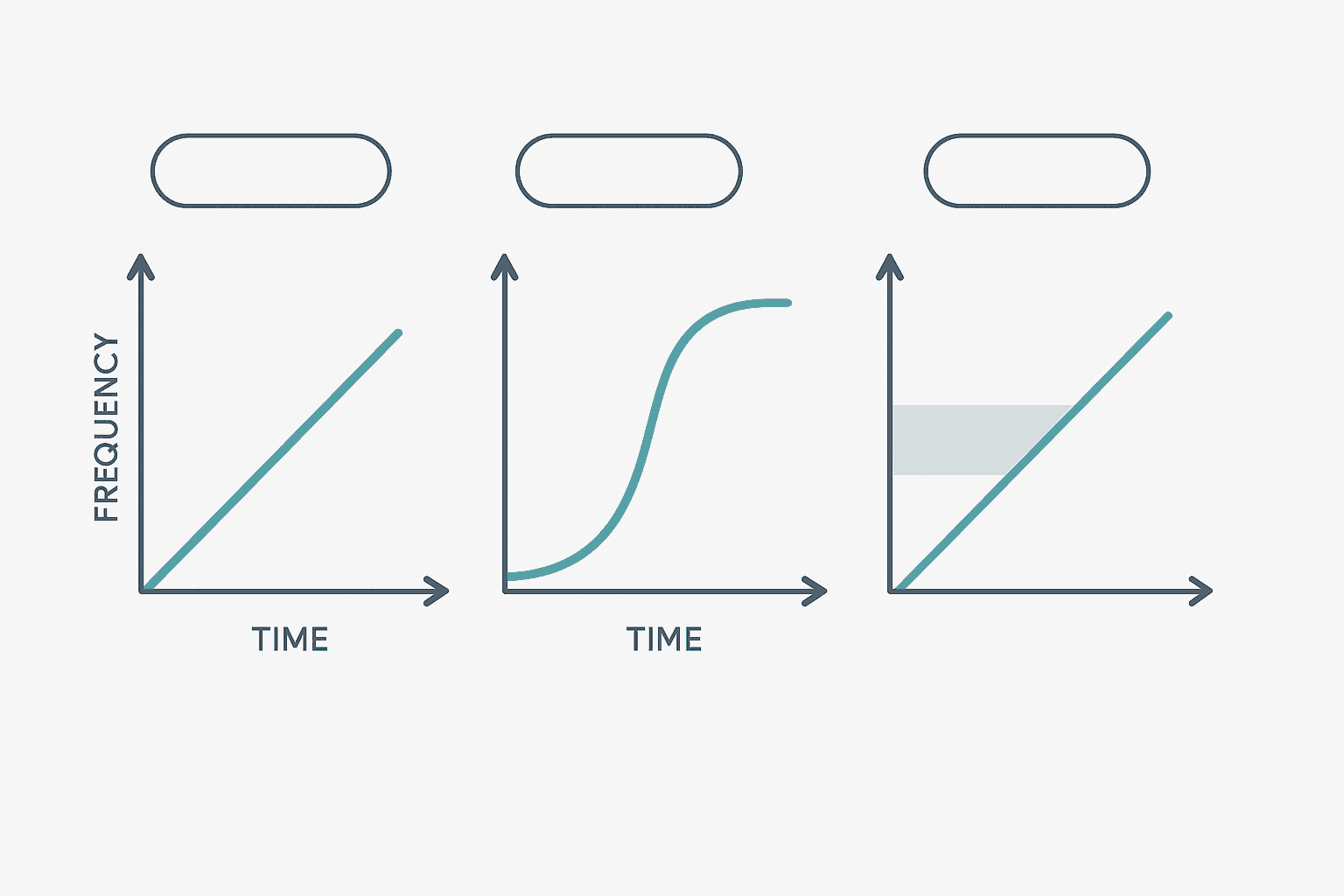
Skip frequencies (also called jump frequencies) tell the drive to avoid a narrow band of output frequencies. If a fan has a mechanical resonance at 35 Hz that causes violent vibration, set a skip band from 33 to 37 Hz and the drive ramps through that range without dwelling. This is a real field fix, not a textbook trick.
Ramp shape (S-curve vs linear) adds a smooth start and end to the acceleration ramp. It reduces mechanical shock on belt drives and gearboxes. Typically set S-curve time to 10 to 20% of accel time. Do not use it on hoist applications where predictable deceleration time is a safety requirement.
A Quick Reference: Parameter Groups and Typical Values
| Parameter Group | Key Setting | Typical Starting Value |
|---|---|---|
| Motor data | Rated current | Nameplate FLA exactly |
| Frequency limits | Max frequency | 50 or 60 Hz (motor rated) |
| Ramp times | Accel time | 5-30 s depending on inertia |
| Control mode | V/Hz or SVC | V/Hz for fans/pumps, SVC for precise apps |
| Reference source | AI or fieldbus | Match to wiring / network |
| Carrier frequency | PWM frequency | 4 kHz general use, 8 kHz for low noise |
PLC Integration: Writing Speed Reference and Reading Drive Status
When the VFD is controlled via a fieldbus, the PLC writes a speed reference (usually 0 to 16384 representing 0 to maximum frequency, depending on the drive profile) and reads back actual speed, current, and fault status each scan. This is where PLC programming and drive commissioning overlap directly. Make sure the drive's node address, baud rate, and protocol parameters match your PLC network configuration exactly. A mismatch here produces a communication fault that looks like a drive fault when it is actually a config error.
On Modbus RTU networks, the drive's Modbus address, baud rate (usually 9600 or 19200), and parity must match the PLC's serial port settings. The Modbus RTU protocol guide and the Modbus register calculator are useful here for working out register addresses. For OPC UA integration to a SCADA layer, see the OPC UA protocol guide for PLC engineers.
Keep Learning
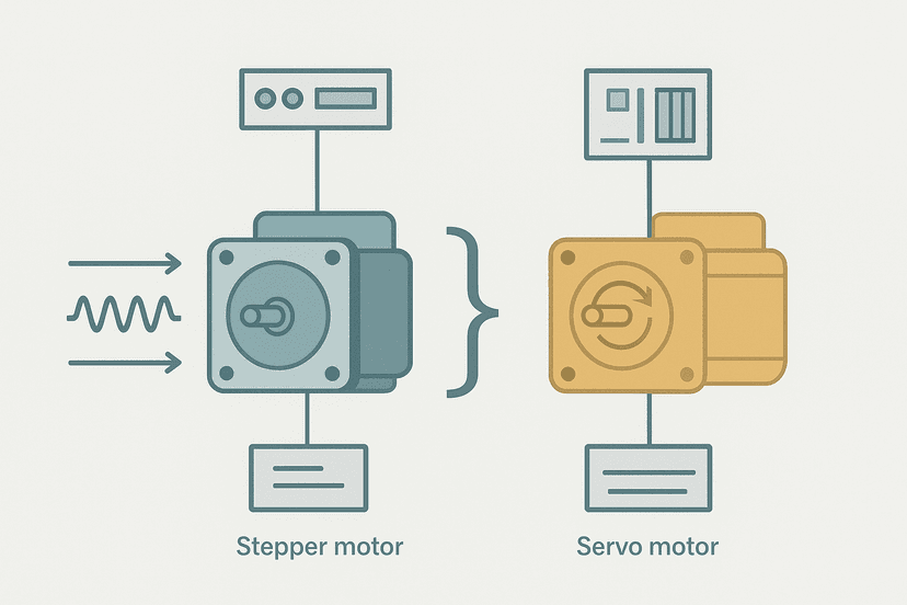
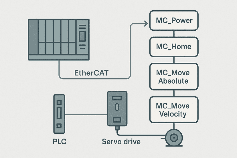
Now that you understand what the key VFD parameters do, the logical next step is knowing what happens when something goes wrong. The VFD fault codes guide maps the most common fault numbers to root causes and fixes. If you are commissioning a more complex motion application, PLCopen motion control function blocks and servo drive PID tuning cover the next level of drive control from the PLC side. And if you need to decide between a stepper and a servo for a new axis, the stepper vs servo motor comparison lays out the trade-offs clearly.
Was this helpful?