VFD Fault Codes: What They Mean and How to Fix Them
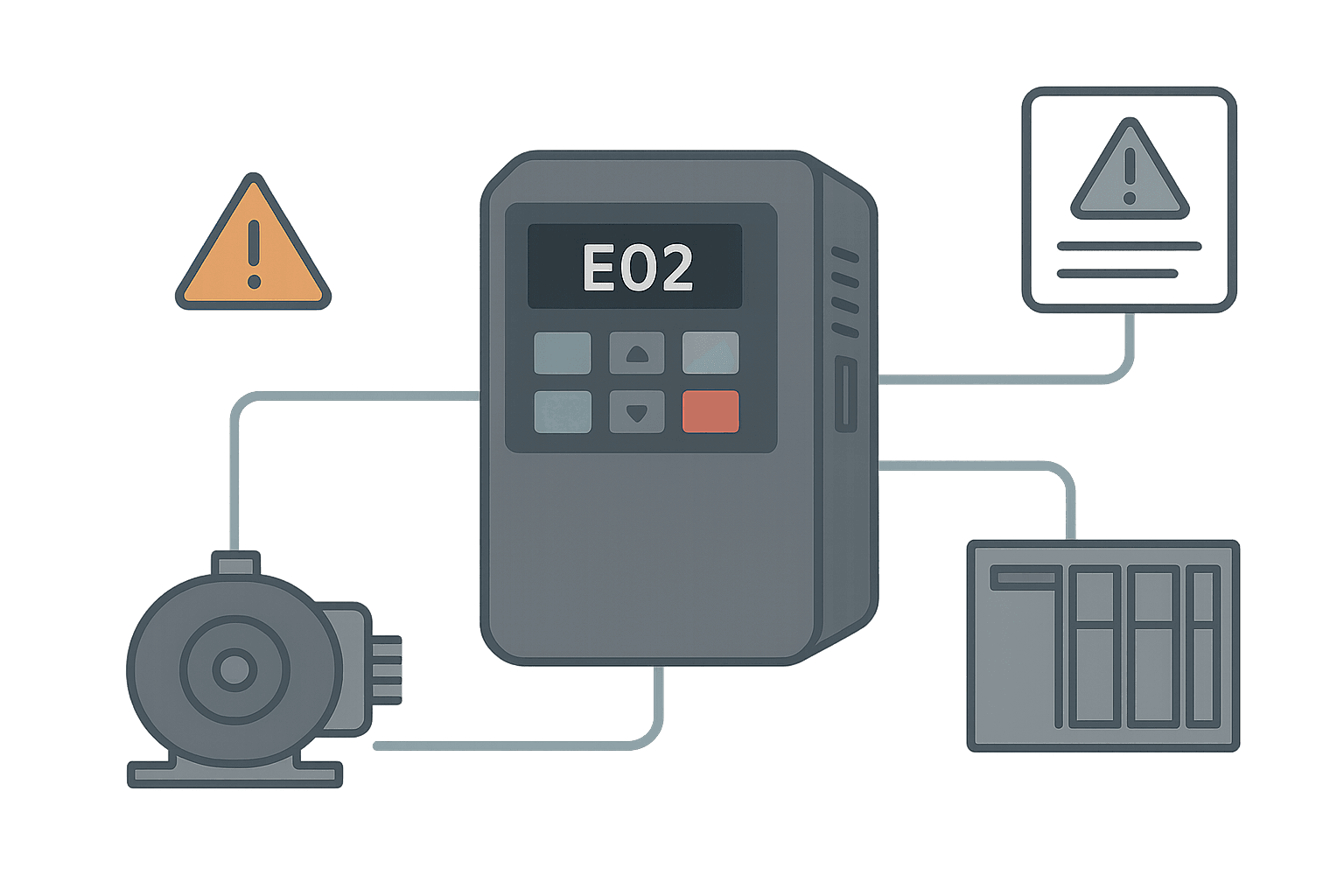
Your line just stopped. The VFD display reads F0022 or OC or E.OHT and the operator is staring at you. You have maybe two minutes to figure out whether this is a nuisance trip you can clear and restart, or a genuine hardware problem that needs a part. That two-minute decision is what this post is about.
Drive fault codes vary by manufacturer and even by product family within the same brand. But underneath the different mnemonics, there are roughly eight fault categories that account for about 90% of everything you will ever see in the field. Understand the category first, then look up the vendor-specific code second.
The Eight Core VFD Fault Categories
| Category | Typical Code Prefixes | Root Cause Group |
|---|---|---|
| Overcurrent | OC, F0001, E001, SC, Err04 | Load, accel ramp, motor wiring, IGBT |
| Overvoltage | OV, F0002, E003, Err05, OU | Regen energy, long decel, supply transients |
| Undervoltage | UV, F0003, LV, E004, Err06 | Supply dip, phase loss, weak DC bus cap |
| Overtemperature | OH, OHT, F0011, E021, THM | Ambient, clogged vents, overload, NTC fault |
| Ground fault | GF, EF, F0021, E009, Err08 | Insulation breakdown, cable length, condensation |
| Overload / motor thermal | OL, OLT, F0031, E005, THR | Motor running hot, duty cycle, wrong motor data |
| Communication loss | CE, ComErr, F0070, E041, Err16 | Network cable, PLC scan, drive parameter |
| Hardware / internal | HW, CPU, F0090, E090, IPM | Driver board, IGBT, firmware, NTC sensor |
Overcurrent Faults: The Most Common Call-Out
Overcurrent faults are the number one reason drives trip on the shop floor. The drive is protecting its output transistors (IGBTs) from being destroyed. Output current has exceeded the drive's instantaneous current limit, typically 150% to 200% of rated for 1 to 60 seconds depending on the drive class.
Before you clear and restart, ask three questions: Did the fault happen at startup, during acceleration, or at running speed? The timing tells you almost everything.
- At startup: Motor or load is seized, wrong motor data entered (nameplate amps too low), or output phases are shorted. Check motor resistance phase-to-phase with a multimeter before restarting.
- During acceleration: Accel time is too short for the inertia. Increase parameter P1120 (Siemens G120) or ACCEL TIME 1 (PowerFlex 525) by 20% and retry. If it still trips, check for a mechanical jam at full load.
- At running speed: Sudden mechanical overload, broken coupling, or the load duty cycle is higher than the motor is rated for. Log the output current trend if your drive supports a data logger or fault history buffer.
Overvoltage Faults: Regenerative Energy and Supply Spikes
An overvoltage fault means the DC bus inside the drive has climbed above the trip threshold. For a 480 V AC drive that is usually around 800 VDC. The most common cause is the motor acting as a generator during deceleration, pushing energy back into the DC bus faster than the internal braking resistor can absorb it.
- Extend the decel ramp. A 3-second decel on a 50 kg flywheel load is asking for trouble. Try 10 to 15 seconds first.
- If your application genuinely needs fast stopping, fit an external braking resistor and enable the braking chopper output. Most drives from 7.5 kW and up have the chopper built in but need a resistor wired to the BR/DB terminals.
- Check your supply for voltage spikes. A 480 V line sitting at 505 V with transients on top will trip an OV fault at light load even with a long decel.
Overtemperature Faults: More Than Just a Hot Room
Drive overtemperature faults (OH, OHT, THM) are almost always one of three things: the cooling fan has failed, the vents are clogged with dust or oil mist, or the drive is running at a high PWM carrier frequency in a 45 C ambient. The fix sounds obvious but there is a gotcha.
Many drives derate their continuous output current when you raise the carrier frequency from the default (typically 4 kHz) to a quieter 8 or 16 kHz to reduce motor noise. If a previous engineer bumped the carrier frequency for acoustic reasons and the load has since increased, you can get thermal trips that look mysterious. Check the carrier frequency parameter first. On a Yaskawa GA700 that is C6-02; on a Siemens G120 it is P1800.
Ground Fault and Insulation Faults
A ground fault code (GF, EF, E009) means the drive has detected current flowing to earth on its output. This is a safety-critical fault and you should not just clear and restart without investigating.
Disconnect the motor and cable from the drive output terminals (U, V, W). Measure insulation resistance from each phase to earth with a 500 VDC megger. A healthy motor will read 100 MOhm or higher on a new winding, and you should be concerned below 1 MOhm. If the motor tests fine, the fault may be in the cable itself, especially long runs in conduit exposed to moisture. Also note: very long cable runs (above 50 to 100 metres) can cause nuisance ground fault trips due to cable capacitance. Adding an output reactor or sine filter between the drive and motor fixes this.
Communication Loss Faults on PLC-Controlled Drives
When a drive is commanded over PROFINET, EtherNet/IP, Modbus RTU or any other fieldbus, a communication loss fault (CE, ComErr, F0070) means the drive has not received a valid telegram within its watchdog timeout window. On most drives that window defaults to 100 to 500 ms.
The fault often comes from the PLC side, not the drive. A program scan overrun, a task configuration change, or even a firmware update on the PLC that altered the EDS/GSDML mapping can kill the connection. Check the PLC's I/O connection status tags first. On a ControlLogix system, look at the ModuleFaultBits in the GSV instruction output or the connection status word in your PROFINET controller diagnostics in TIA Portal.
If you are using Modbus RTU, a common cause is a parameter mismatch after someone replaced a drive and forgot to set the baud rate or station address. Check the drive's comms parameters against your PLC's Modbus configuration. The Modbus RTU Protocol Explained post covers the timing and framing rules that matter here.
Reading the Fault History Buffer
Every modern drive stores a fault history, usually the last 4 to 10 faults with a timestamp (or at minimum an elapsed-hours counter). This is your best diagnostic tool and most engineers never use it properly.
- Siemens G120 / G120C: Navigate to r0947 (fault code) and r0948 (fault time). You can read these via the BOP-2 keypad or directly as drive parameters in TIA Portal's drive commissioning view.
- Allen-Bradley PowerFlex 525 / 755: Parameter 6 (Fault 1 Code) through Fault 10. The 755 adds a full data log with current, voltage and speed at the moment of trip.
- Mitsubishi FR-E800 / FR-A800: Use Pr.E.ERR or the Fault History display (H---) accessible from the parameter unit. Eight faults are stored with output frequency, current and voltage at trip.
- Yaskawa GA700: U2-01 through U2-20 give you the last fault plus the operating conditions at the time of trip. Extremely useful for diagnosing intermittent OC faults.
PLC Ladder Logic for Drive Fault Monitoring
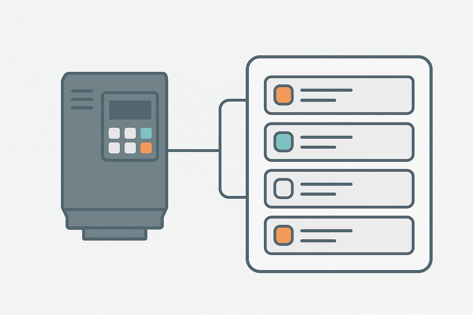
Most plants rely on an operator seeing the drive keypad flash. A better approach is to read the drive fault code into your PLC over the fieldbus and latch an alarm with a one-shot so you capture the first fault even if the drive auto-resets. Here is a practical rung pattern for a PowerFlex 525 over EtherNet/IP where the drive fault code lands in a DINT tag.
Drive Fault Detection and Alarm Latch (Rockwell Studio 5000). Ladder logic (2 rungs): Rung 0: examine if Drive1_FaultCode.0 is on (XIC), then examine if Drive1_FaultAck is off (XIO), then latch output Drive1_FaultAlarm (OTL). Rung 1: examine if Drive1_FaultAlarm is on (XIC), then examine if Drive1_FaultAck is on (XIC), then unlatch output Drive1_FaultAlarm (OTU). Rung 1: Drive1_FaultCode.0 is the fault bit mapped from the PowerFlex 525 status word (bit 0 of the fault word goes high on any fault). XIO(Drive1_FaultAck) prevents the alarm from re-latching while the operator has already acknowledged it. OTL latches the alarm coil. Rung 2: Once the fault is cleared AND the operator presses the acknowledge pushbutton (Drive1_FaultAck), OTU unlatches the alarm.
The diagram above evaluates one scan. Run these exact rungs on a real scan cycle to watch the latching and the timers behave.
Run this in the simulatorVendor-Specific Quirks Worth Knowing
Siemens G120: Faults and alarms are separate. A fault (Fxxxx) requires a reset. An alarm (Axxxx) is informational and self-clears. Engineers often miss A-codes entirely because the drive keeps running. Watch A07921 (motor overtemperature pre-warning) before it becomes F07011.
Allen-Bradley PowerFlex 755: The 755 distinguishes between a fault, a major fault and a minor fault. A minor fault can be configured to allow continued operation. Check Fault Config 1 (P935) to see what your predecessor decided to suppress. Suppressed faults are a common source of mystery failures months later.
SEW MOVIDRIVE / MOVITRAC: SEW uses a two-part code, for example F1210 where the first digit is the fault class and the remaining digits are the specific error. The SEW MOVITOOLS MotionStudio software shows a plain-text description. Without the software, the keypad only shows the numeric code and you need the manual for that specific firmware revision.
Lenze 8400: Lenze uses an Event Code system (Cxxxx). The keypad shows the code; the full description requires the Lenze Engineer software or the PDF manual. Lenze's manuals are well-structured and available free on their website. Always download the manual that matches the firmware version shown on the drive nameplate.
A Systematic Fault Response Checklist
- Record the exact fault code and the time of trip before clearing anything.
- Read the fault history buffer for the last 3 to 5 faults. Look for a pattern: same fault, same time of day, same production conditions.
- Check the drive display for output current, DC bus voltage and heatsink temperature at the moment of fault if available.
- Identify the fault category (overcurrent, OV, UV, thermal, ground, comms, hardware) and follow the category-specific checks above.
- Correct the root cause. Clear the fault only after you have a credible explanation.
- Restart and monitor for the first 5 minutes. If the fault returns, do not keep cycling power. You are making the diagnosis harder and risking component damage.
- Log the fault, the cause, and the fix in your maintenance system. Drives that trip once will often trip again.
When the Fault Code Points to Hardware
Hardware fault codes (HW, IPM, CPU, driver fault) are the ones that hurt. An IPM fault on a Mitsubishi or Yaskawa drive usually means the IGBT module has taken a hit, either from a sustained overcurrent that your protection did not catch fast enough, or from a DC bus transient. At this point you are looking at a board-level repair or a drive swap.
Before you order a new drive, check the obvious things: control power supply voltage (usually 24 VDC), the NTC thermistor resistance (typically 10 kOhm at 25 C, dropping to 1 to 2 kOhm at 80 C), and whether the fault code clears after a full power-down and 5-minute wait for the DC bus to discharge. Some internal faults are caused by a latched processor state and clear with a real power cycle, not just a reset command.
If you are replacing a drive and want to make sure the panel protection is right, the Fuse vs Breaker Selection for Control Panels post covers the input protection side that sits upstream of the drive.
Frequently asked questions
How do I reset a VFD fault code?
What does an overcurrent (OC) fault on a VFD mean?
Why does my drive keep faulting on overvoltage during stopping?
Can I find VFD fault code meanings without the manual?
What is the difference between a VFD fault and an alarm?
How do I know if a VFD hardware fault means I need a new drive?
Learn this by building it
There is a PLC in this site. It runs a real scan engine, checks your logic against the same tests a working machine would fail, and needs no download and no account.
Open the exercisesFree, no signup, runs in your browser. See all 16 exercises.
Was this helpful?