ISO 13849-1 PL Levels: What They Mean in Practice
If you have spent any time on a CE marking project for machinery, you have seen the term Performance Level. It sits at the centre of ISO 13849-1, the machinery safety standard that applies to most electromechanical safety functions, from emergency stops and guard interlocks to two-hand controls and enabling devices. Yet the PLa-to-PLe scale confuses a lot of engineers who are used to thinking in SIL terms. This post walks through what PL actually measures, how you determine which PL you need, and how you verify that your design delivers it.
What Is ISO 13849-1 Performance Level?
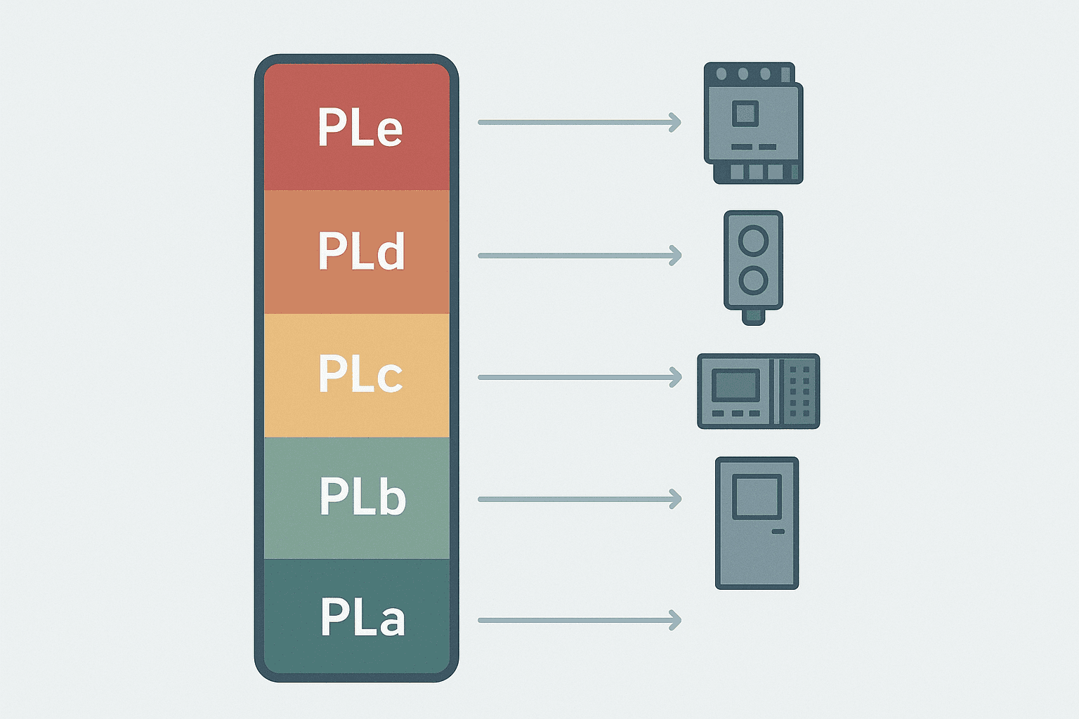
ISO 13849-1 Performance Level (PL) is a five-tier rating, PLa through PLe, that quantifies the probability of a safety function failing dangerously per hour of operation. Each tier corresponds to a PFHd range: PLa covers 1e-4 to 1e-5 per hour at the low-reliability end, and PLe covers 1e-7 to 1e-8 per hour at the high-reliability end. The standard defines a design method for determining which PL a hazard demands (PLr, required) and for calculating what your actual design achieves (PL), so you can confirm the achieved PL meets or exceeds PLr.
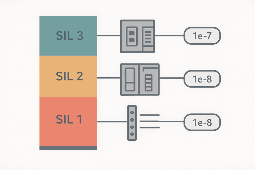
| Performance Level | PFHd range (per hour) | Equivalent SIL |
|---|---|---|
| PLa | 1e-5 to less than 1e-4 | No SIL equivalent |
| PLb | 3e-6 to less than 1e-5 | SIL 1 |
| PLc | 1e-6 to less than 3e-6 | SIL 1 |
| PLd | 1e-7 to less than 1e-6 | SIL 2 |
| PLe | 1e-8 to less than 1e-7 | SIL 3 |
Step 1: Find the Required PL Using the Risk Graph
ISO 13849-1 Annex A contains a risk graph with three parameters. Severity (S) is either S1 (reversible injury) or S2 (irreversible injury or death). Frequency of exposure (F) is either F1 (rarely to infrequently, less than 1 hour per shift) or F2 (frequently to continuously). Possibility of avoidance (P) is either P1 (possible under certain conditions) or P2 (scarcely possible). You follow the branches and arrive at a starting point labelled a, b, c, d or e, which becomes your PLr.
A practical example: a press with a fixed guard interlock. If the guard is opened during the press stroke, the operator could receive a crush injury that is irreversible (S2). Access happens during every production cycle for tool changes, so frequency is F2. Because the press ram moves at speed with no early warning, avoidance is P2. The risk graph lands at PLe. That is the level the safety function must achieve. Compare that to a light curtain on a slower assembly cell where the worst credible injury is hand laceration (S1), access is infrequent (F1) and there is time to step back (P1): you land at PLc.
Step 2: Choose an Architecture (Category B to 4)
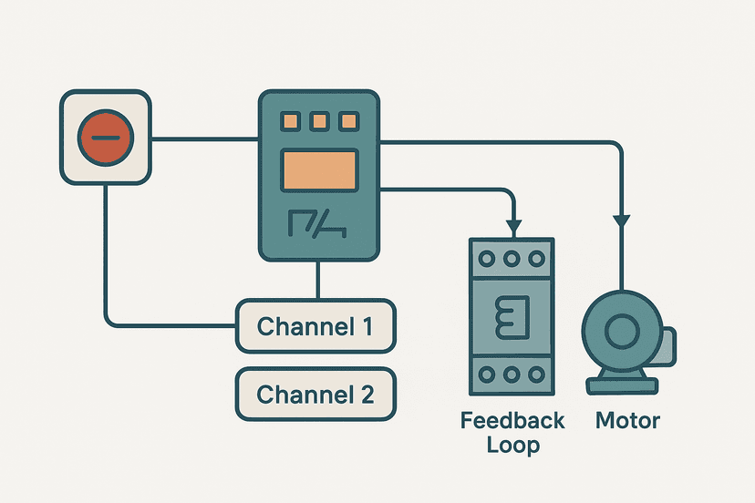
ISO 13849-1 defines five structural categories that describe how a safety function is built. Category B is a single-channel system with no specific requirements beyond using suitable components. Category 1 adds the requirement for well-tried components and well-tried safety principles. Categories 2, 3 and 4 introduce automatic testing, redundancy and cross-channel monitoring.
- Category B: single channel, no self-test, basic components. Maximum achievable PL is PLb with high-quality components.
- Category 1: single channel, well-tried components (proven in field use or by analysis). Maximum PLc.
- Category 2: single channel plus test channel that checks the safety function at intervals. Maximum PLd with high MTTFd and DCavg.
- Category 3: dual channel, single fault does not cause loss of the safety function, fault detected at next demand. Maximum PLd.
- Category 4: dual channel, single fault detected immediately by diagnostics, no accumulation of undetected faults. Maximum PLe.
The category alone does not determine the PL. You also need to know the MTTFd of each channel and the DCavg of the diagnostic measures. All three inputs (category, MTTFd, DCavg) feed into the K-chart in ISO 13849-1 clause 6 to give you the achieved PL. This is where the work happens.
Step 3: Calculate MTTFd from B10d Data
MTTFd (Mean Time To dangerous Failure) is calculated from the B10d value your component manufacturer publishes. B10d is the number of cycles at which 10% of the population has failed dangerously. The formula is straightforward:
MTTFd = B10d / (0.1 * nop)

Where:
  B10d = dangerous B10 value from manufacturer datasheet (cycles)
  nop  = number of operating cycles per year

Example:
  B10d = 2,000,000 cycles (typical safety door switch)
  nop  = 20 cycles/hour * 8 hours/day * 250 days/year = 40,000 cycles/year

  MTTFd = 2,000,000 / (0.1 * 40,000)
         = 2,000,000 / 4,000
         = 500 years  --> capped at 100 years per ISO 13849-1 clause 6.2.4
ISO 13849-1 caps MTTFd at 100 years per channel for calculation purposes, so anything above that is treated as 100 years. The standard also caps the combined MTTFd for dual-channel (Category 3 or 4) systems at 2,500 years to prevent over-crediting redundancy.
Step 4: Assign DCavg
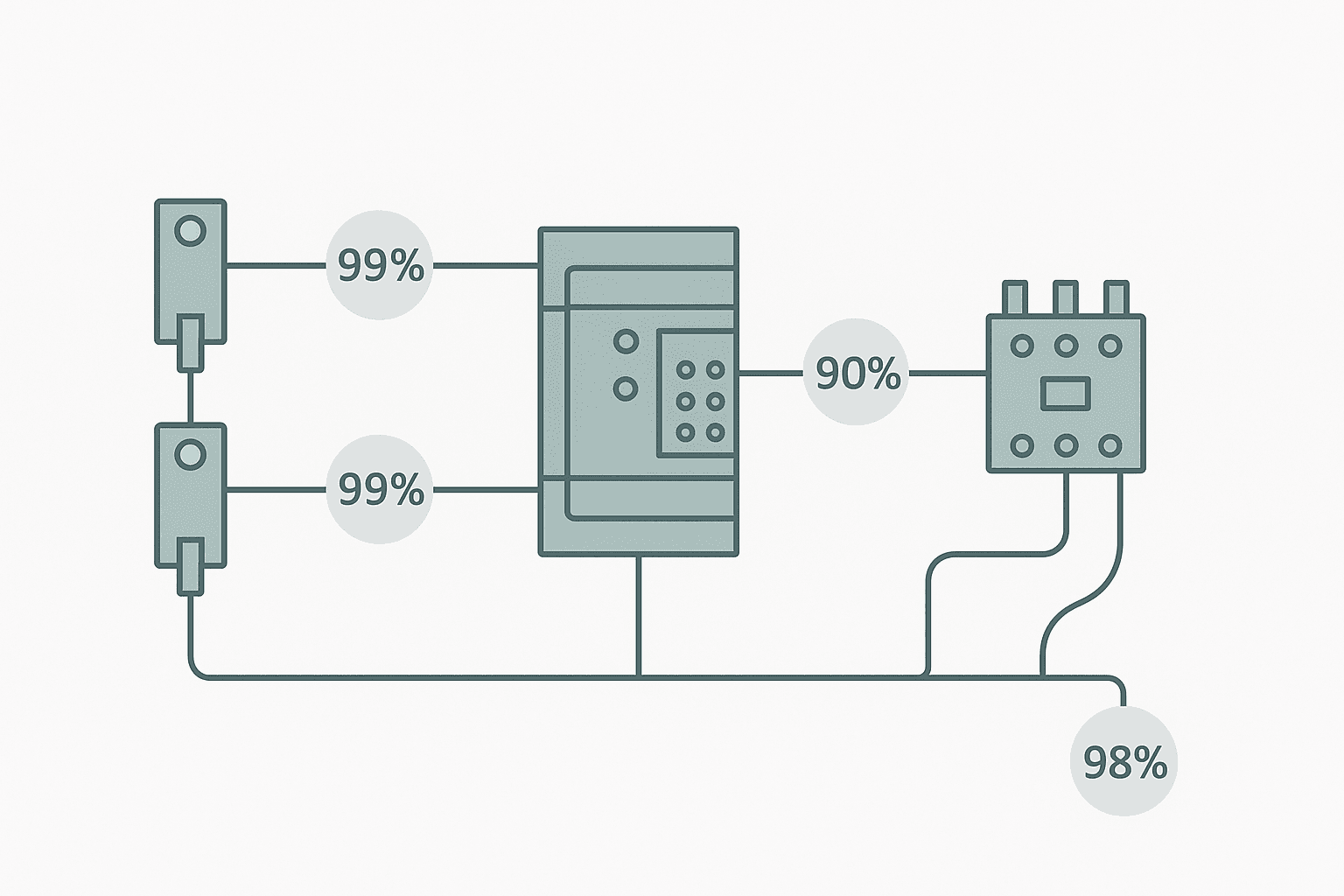
Diagnostic Coverage average (DCavg) represents how much of the dangerous failure rate is detected by self-test, cross-monitoring or functional testing. ISO 13849-1 Table E.1 lists measures and their DC values. Cross-monitoring of two channels where both must agree gives DC = 99% (high). A simple plausibility check (one channel, tested at start-up only) might give DC = 60% (low). You calculate DCavg across all components in the safety function weighted by their individual failure rates.
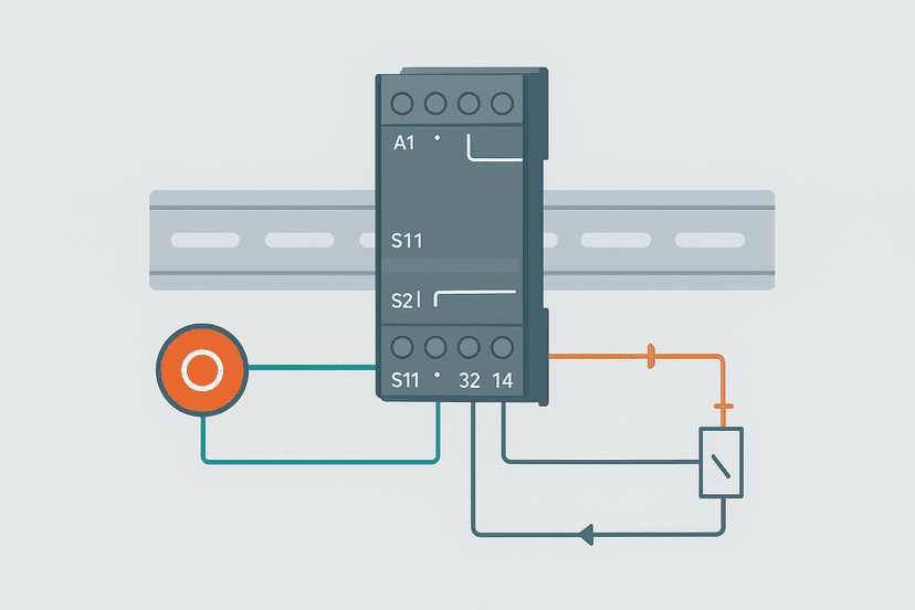
In practice, if you are using a certified safety relay (such as a Pilz PNOZ or Schmersal SRB family) or a safety PLC (like a Siemens ET 200SP F-CPU), the manufacturer has already established the DC contribution of the device's internal diagnostics. You still need to account for DC on the field devices: sensors, actuators and wiring. This is where engineers often underestimate effort. A safety door switch wired to a safety relay with EDM (External Device Monitoring) on the output contactor gives you a credible system-level DC; a switch wired identically but without EDM does not.
Common Cause Failure: The Score You Cannot Ignore
For Categories 3 and 4, you must also address Common Cause Failure (CCF). A CCF is any single event, such as a wiring short, a flood or an EMC burst, that defeats both channels at once, making redundancy useless. ISO 13849-1 Annex F gives a 100-point scoring table covering eight measure groups: separation/segregation, diversity, design/application/experience, analysis/testing, competence/training, environmental measures, maintenance and environmental testing. You must reach a total of 65 points or more to claim Category 3 or 4. If you score below 65, your architecture drops to Category 2 regardless of channel count.
On one robotics cell commissioning I worked on, we had Category 3 on paper but scored only 58 on the CCF table because the two encoder channels ran in the same cable trunking as the motor power cables. Adding a separate conduit for the safety channels and using encoders from two different manufacturers (diversity) pushed the score to 72. It was a half-day of re-routing that saved us a complete redesign.
Reading the K-Chart to Confirm Achieved PL
Once you have MTTFd, DCavg and a Category, you look up the achieved PL in the K-chart (Figure 5 in ISO 13849-1). The chart plots category on the x-axis and MTTFd ranges (low 3-10 years, medium 10-30 years, high 30-100 years) against PL on the y-axis, with DCavg bands separating cells. A Category 3 design with high MTTFd and DCavg in the medium range (60-90%) achieves PLd. The same architecture with DCavg in the high range (90-99%) still achieves PLd but with more margin. Only Category 4 with high MTTFd and high DCavg reaches PLe.
ISO 13849-1 vs IEC 62061: Which Standard Applies?
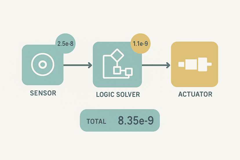
Both standards are harmonised under the EU Machinery Directive and its successor, the Machinery Regulation (EU) 2023/1230. The short rule is: if your safety function uses exclusively electromechanical or hydraulic/pneumatic components, use ISO 13849-1. If it uses complex electronic or programmable electronic components (safety PLCs, drives with safety-rated firmware, ASICs), IEC 62061 is the primary standard, though ISO 13849-1 can still be applied to the non-electronic parts. In practice, most modern machine safety systems mix both, so engineers use ISO 13849-1 for the input devices and output actuators and IEC 62061 for the safety logic solver, then combine the PFHd values.
The IEC 62061 SIL levels guide on this site covers the SIL side of that calculation in detail, and the IEC 62061 PFHd calculation guide shows how to combine subsystem PFHd values end-to-end. For the wiring side of any safety function, the safety relay wiring guide and the emergency stop circuit categories post are the natural companion reads.
Practical Tips for Getting PL Right First Time
- Collect B10d data before you select components, not after. Some suppliers do not publish it; that is a red flag for safety-rated use.
- Use SISTEMA (free from IFA) to run calculations and generate an audit trail. Manual K-chart lookups are fine for a single function, but a machine with 15 safety functions needs a tool.
- Do not mix up B10 and B10d. If only B10 is available, contact the manufacturer for the dangerous failure fraction rather than assuming 50%.
- Run a CCF score early. If you are planning Category 3 or 4, confirm you can reach 65 points before the panel is built. Cable routing changes are cheap at drawing stage.
- Validate each safety function at commissioning with a functional test: apply the demand, confirm the safe state, measure the response time and compare it to the required stopping time from your risk assessment.
- Keep your validation documents under version control. A machine modified two years after CE marking needs an updated assessment, and you will want the original baseline to compare against.
Related Reading
- VFD Fault Codes: What They Mean and How to Fix Them
- SCADA vs PLC: How They Work Together on the Plant Floor
- HMI and SCADA: How They Fit Together in a Real Plant
Keep Learning
Performance Level gives you the what; the next step is the how. The IEC 62061 PFHd calculation guide shows you how to combine subsystem failure rates into a total safety function PFHd, which you need when mixing ISO 13849-1 and IEC 62061 subsystems. For the hardware side, safety relay wiring circuits covers the Category 3 and 4 wiring patterns that deliver the architecture your PL calculation assumes. And if you are building the safety logic in a Siemens F-CPU, the S7-1200 vs S7-1500 comparison will help you decide which platform has the safety rating your PLd or PLe application demands.
Was this helpful?