Tank Fill Control PLC Exercise: Ladder Logic
A tank fill sequence is one of the first real-world problems you should build in ladder logic. It has everything: sensor inputs, timed sequences, output interlocks, and a fault that can cause a physical mess if you get the logic wrong. This exercise walks you through a complete two-setpoint tank fill program in Studio 5000 (Allen-Bradley ControlLogix or CompactLogix), from the I/O table all the way to the fault latch and operator reset. You can adapt every rung to any platform.
What Is a Tank Fill Control PLC Exercise?
A tank fill control PLC exercise is a structured ladder logic program that automatically fills a tank to a high-level setpoint, stops filling, and waits until the level drops to a low-level setpoint before filling again. The PLC monitors discrete level switches, controls an inlet solenoid valve and a fill pump, and latches a fault if the tank overflows or if the fill cycle takes too long. It is the foundation for real liquid-handling applications like chemical dosing, buffer tanks, and process water systems.
The Scenario and I/O Table
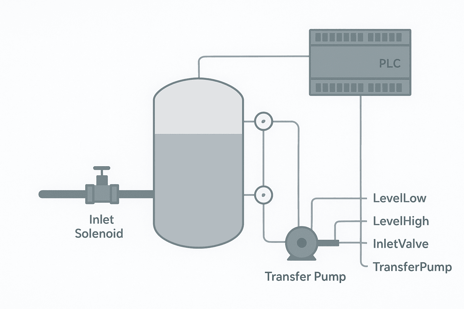
Picture a 500-litre stainless buffer tank. Water enters through a pneumatic inlet valve; a transfer pump on the outlet feeds a downstream process. Two float switches monitor level: one at 20% (low) and one at 90% (high). A third switch at 98% is the high-high trip, wired hardwired AND in software. The HMI has a Start/Stop pushbutton and a Fault Acknowledge button.
| Tag Name | I/O Type | Address | Description |
|---|---|---|---|
| Level_Low | DI | Local:1:I.Data.0 | Float switch, closes at 20% level |
| Level_High | DI | Local:1:I.Data.1 | Float switch, closes at 90% level |
| Level_HighHigh | DI | Local:1:I.Data.2 | Float switch, closes at 98% (trip) |
| HMI_Start | DI | Local:1:I.Data.3 | Operator start command from HMI |
| HMI_Stop | DI | Local:1:I.Data.4 | Operator stop command from HMI |
| HMI_FaultAck | DI | Local:1:I.Data.5 | Fault acknowledge from HMI |
| Inlet_Valve | DO | Local:2:O.Data.0 | Pneumatic inlet valve, energise to open |
| Fill_Pump | DO | Local:2:O.Data.1 | Fill pump contactor |
If you need a refresher on how PNP and NPN level switches connect to your input module, the post on 3-wire sensor wiring for PNP and NPN devices covers it clearly. And if you are unsure whether your input module is sinking or sourcing, sinking vs sourcing PLC I/O explains the difference with real wiring diagrams.
Sequence Design Before You Write a Rung
Write down the sequence in plain English first. It sounds obvious, but skipping this step is why people end up with latching logic that never resets. Here is the sequence for this exercise:
- Operator presses HMI Start. System is enabled.
- If Level_Low is TRUE (tank at or below 20%), open Inlet_Valve.
- After a 2-second valve-open delay, start Fill_Pump.
- When Level_High goes TRUE (tank at 90%), stop Fill_Pump first, then close Inlet_Valve.
- Wait. When level drops and Level_Low goes TRUE again, repeat from step 2.
- If Level_HighHigh goes TRUE at any time, latch a High_High_Fault, stop everything, and wait for HMI_FaultAck.
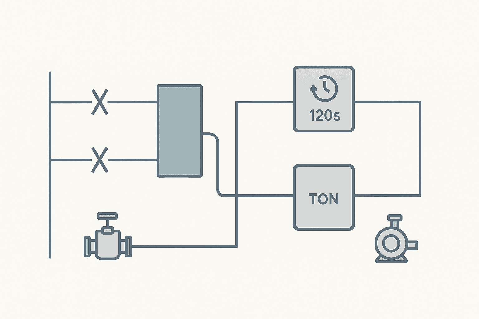
- If the fill cycle runs longer than 120 seconds without reaching Level_High, latch a Fill_Timeout_Fault.
- Operator presses HMI Stop to disable the system cleanly.
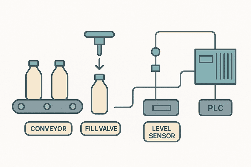
Notice the pump stops before the valve closes in step 4. This prevents water hammer from closing the valve against a running pump. Small detail, but it matters on real pipework. You see the same sequencing logic in the PLC pump station exercise and in the bottle filling machine project, both of which extend this pattern with multiple pumps and product counters.
Tank Fill Ladder Logic: Rung by Rung
The ladder below is written for Studio 5000 notation. XIC is a normally open contact, XIO is a normally closed contact, OTL latches a bit ON, OTU unlatches it, and OSR is a one-shot rising edge. TON is a retentive-on-delay timer. If you are on Siemens TIA Portal, the logic maps directly: use SR/RS function blocks for latches and the IEC TON block. The XIC vs XIO explainer is worth bookmarking if contact types trip you up.
Tank Fill Control: System Enable, Fill Sequence, Fault Latch, and Timeout (Studio 5000). Ladder logic (12 rungs): Rung 0: examine if HMI_Start is on (XIC), then examine if HMI_Stop is off (XIO), then examine if High_High_Fault is off (XIO), then examine if Fill_Timeout_Fault is off (XIO), then latch output System_Enabled (OTL). Rung 1: examine if HMI_Stop is on (XIC), then unlatch output System_Enabled (OTU). Rung 2: examine if System_Enabled is on (XIC), then examine if Level_High is off (XIO), then examine if High_High_Fault is off (XIO), then latch output Fill_Active (OTL). Rung 3: examine if Level_High is on (XIC), then unlatch output Fill_Active (OTU). Rung 4: examine if Fill_Active is on (XIC), then energize output Inlet_Valve (OTE). Rung 5: examine if Fill_Active is on (XIC), then TON on Valve_Open_Delay. Rung 6: examine if Valve_Open_Delay.DN is on (XIC), then examine if Level_High is off (XIO), then examine if High_High_Fault is off (XIO), then energize output Fill_Pump (OTE). Rung 7: examine if Fill_Active is on (XIC), then TON on Fill_Timeout. Rung 8: examine if Fill_Timeout.DN is on (XIC), then examine if Level_High is off (XIO), then examine if Timeout_OS is on (XIC), then latch output Fill_Timeout_Fault (OTL). Rung 9: examine if Level_HighHigh is on (XIC), then examine if HH_OS is on (XIC), then latch output High_High_Fault (OTL). Rung 10: examine if High_High_Fault is on (XIC), then examine if HMI_FaultAck is on (XIC), then examine if Level_HighHigh is off (XIO), then unlatch output High_High_Fault (OTU). Rung 11: examine if Fill_Timeout_Fault is on (XIC), then examine if HMI_FaultAck is on (XIC), then examine if Fill_Active is off (XIO), then unlatch output Fill_Timeout_Fault (OTU). Rung 1 latches System_Enabled on HMI Start, blocked by either fault. Rung 2 unlatches on HMI Stop. Rung 3 latches Fill_Active when the tank is below the high-level setpoint; rung 4 unlatches it when Level_High trips. Rung 5 drives the Inlet_Valve output. Rung 6 starts the 2-second valve-open delay timer. Rung 7 energises Fill_Pump only after the valve delay expires and the tank is not full. Rung 8 runs the 120-second fill timeout timer. Rung 9 latches Fill_Timeout_Fault on a one-shot if the timer expires before Level_High closes. Rung 10 latches High_High_Fault on the rising edge of the 98% switch. Rungs 11-12 unlatch each fault only when the operator acknowledges AND the triggering condition has cleared.
The diagram above evaluates one scan. Run these exact rungs on a real scan cycle to watch the latching and the timers behave.
Run this in the simulatorWhy the Fault Latch Uses OSR (One-Shot Rising)
Driving OTL directly from Level_HighHigh without a one-shot seems simpler, but it creates a problem: if the float switch bounces or the level hovers right at the setpoint, the OTL instruction fires repeatedly and the unlatch logic fights it. The OSR catches exactly one rising edge per event. The fault latches once, stays latched, and only clears on a deliberate acknowledge. This pattern is described in more detail in the post on normally open vs normally closed contacts in ladder logic.
The Fill Timeout: Picking a Realistic Preset
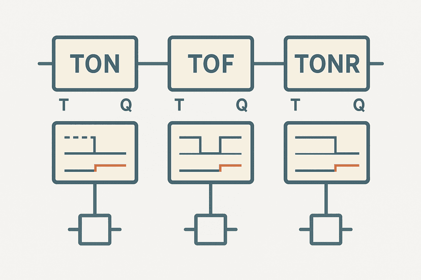
120 seconds is a placeholder. You need to calculate it for your tank. Take the tank volume between Level_Low and Level_High (say 400 litres), divide by your minimum inlet flow rate (say 5 litres per second), and add 30% margin. In this example: 400/5 = 80 seconds, plus 30% = 104 seconds, round to 110. If your inlet flow rate changes with supply pressure, use the worst-case low-flow rate. The TON, TOF and TONR timer explainer is useful if you want to understand how the timer accumulator behaves across scan cycles.
Adding a Cycle Counter for Maintenance Tracking
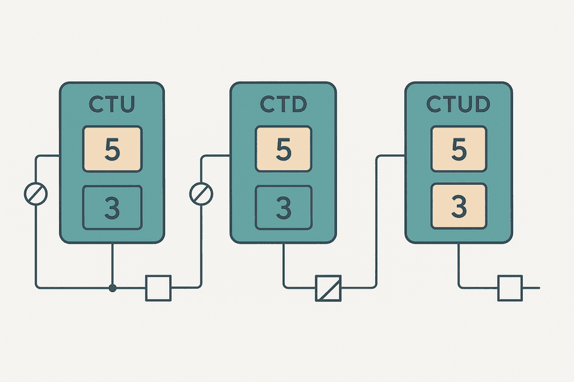
Once the basic sequence is working, add a CTU counter to track fill cycles. Drive it from an OSR on the rising edge of Level_High (the fill-complete event). Display the accumulated value on your HMI and reset it after a maintenance interval. The PLC counter instructions post shows exactly how CTU, CTD and CTUD work, which saves time when you wire in the reset logic.
Extending the Exercise: Analog Level Feedback
The two-switch version is solid for learning, but real tanks often have a 4-20 mA ultrasonic or hydrostatic level transmitter alongside the discrete switches. The transmitter gives you a continuous percentage so you can display a level bar on the HMI and catch a slow leak (level dropping when Fill_Active is FALSE). Wiring and scaling that signal is covered step by step in PLC analog input wiring for 4-20 mA and the matching 4-20 mA scaling formula guide. Once you have the raw count, use the analog scaling calculator to check your EU conversion numbers before you type them into the program.
Testing and Troubleshooting the Exercise
Before connecting real field devices, simulate the program by forcing input bits in online mode. Run through every branch:
- Force HMI_Start TRUE: System_Enabled should latch ON.
- Force Level_Low TRUE with Level_High FALSE: Fill_Active should latch, Inlet_Valve output should energise, and Fill_Pump should come on after 2 seconds.
- Force Level_High TRUE: Fill_Pump should drop out immediately, then Inlet_Valve should de-energise as Fill_Active unlatches.
- Force Level_HighHigh TRUE: High_High_Fault should latch, Inlet_Valve and Fill_Pump should both drop out. Confirm they stay out even if you force Level_Low TRUE.
- Acknowledge the fault with HMI_FaultAck TRUE while Level_HighHigh is FALSE: High_High_Fault should unlatch.
- Let Fill_Timeout accumulate to 120 seconds without Level_High going TRUE: Fill_Timeout_Fault should latch.
If you do not have hardware, the post on how to simulate ladder logic without a PLC covers software emulation options. For testing with real I/O, how to test a PLC input and PLC I/O fault diagnosis with a multimeter are the right next reads.
What to Read Next
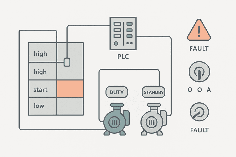
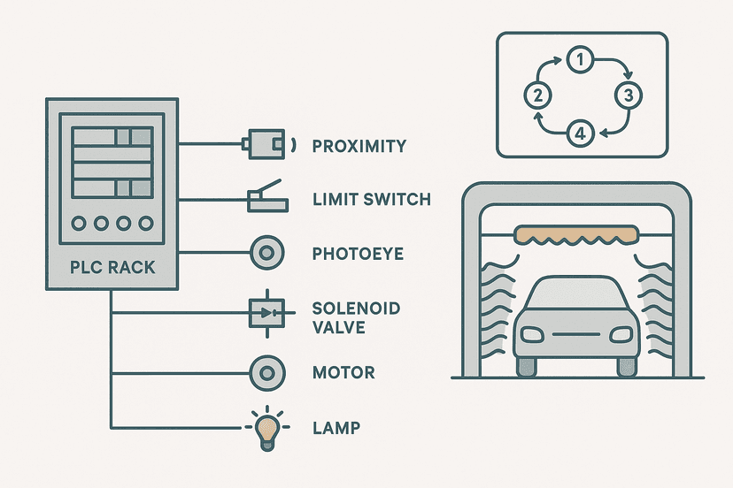
The tank fill sequence is a great foundation. From here, try the PLC pump station exercise to add duty/standby pump alternation on top of your fill logic, or work through the car wash PLC exercise to practice multi-step sequencing with timer-driven state transitions. If you want to push the analog side, add a 4-20 mA level transmitter and scale it with the steps in 4-20 mA scaling in a PLC using ST and ladder.
Frequently asked questions
What sensors does a tank fill PLC program typically use?
Should the inlet valve or the pump start first in a fill sequence?
How do I stop the tank from overfilling if the high-level switch fails?
What is the difference between a latched fault and a regular interlock in ladder logic?
How do I add a fill timeout to a tank fill program?
Can I use a PLC counter to track the number of fill cycles?
What I/O types do level switches connect to on a PLC?
How do I simulate a tank fill program without a real tank?
Do I need an analog input for a basic tank fill exercise?
How do I wire a 3-wire PNP level switch to a Studio 5000 digital input?
Now build it
You have just read about ONS and CTU and CTD. Reading a rung and making one behave are different skills, and the second one is the job.
Batch Counter (CTU + RES)
Intermediateabout 15 minCount parts passing a sensor; after 4 parts the batch is done and a lamp turns on. A reset button starts the next batch. Counters count RUNG EDGES: a part sitting on the sensor counts once, not forever.
Build this rungFree, no signup, runs in your browser. See all 16 exercises.
Was this helpful?