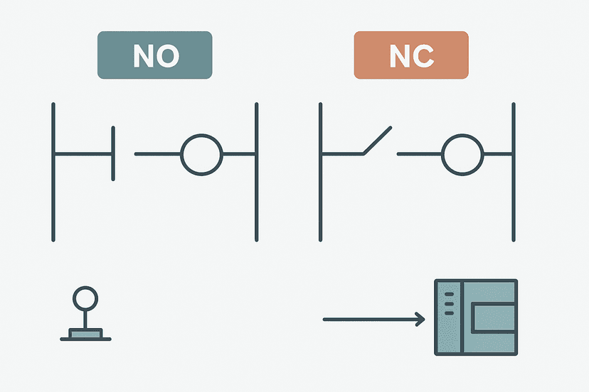
How to Simulate Ladder Logic Without a PLC
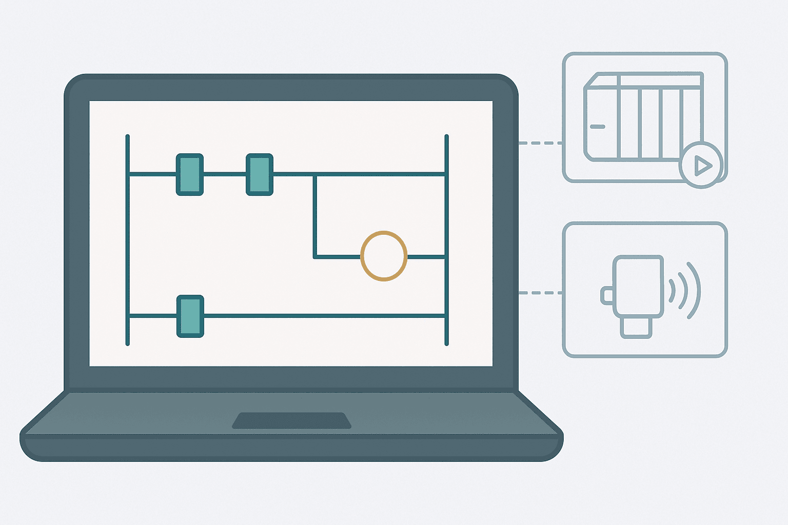
You've written a few hundred rungs of ladder logic and the hardware is still six weeks away. Or maybe the machine is live and you want to test a change without stopping production. Either way, simulating ladder logic on your PC is one of the most practical skills an automation engineer can have, and most people never use it to its full potential.
What Does It Mean to Simulate Ladder Logic?
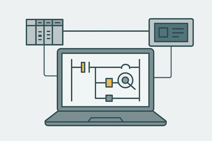
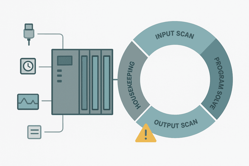
Simulating ladder logic means executing your program in a software environment on a PC rather than on physical PLC hardware. The simulator evaluates every rung each scan cycle, updates coil states, runs timers and counters, and lets you force input bits manually. You get a live view of contact states, tag values and timer accumulators without wiring a single terminal. Most modern simulators run the actual vendor firmware, so instruction behaviour is very close to the real controller.
Why Simulate Before Commissioning?
The honest answer: it saves embarrassing hours on site. I once spent most of a commissioning day chasing a sequencer that would lock up in step 4 under a specific fault-reset sequence. The bug was obvious in hindsight, a latch that couldn't clear because the fault bit was still true, but it took two engineers and a machine shutdown to find it in the panel. Running a simulation for 20 minutes beforehand would have caught it at the desk.
Beyond catching bugs, simulation lets you verify timer values, walk through interlock sequences, and demo logic to operators before the machine arrives. If you're working on a project with PLC troubleshooting using online monitoring later in the job, simulation is the offline equivalent: the same forced-input, watch-the-rungs-update workflow, but without live power.
The Main Simulation Tools by Platform
| Platform | Tool | Included? | HMI Connect? |
|---|---|---|---|
| Rockwell Studio 5000 | Logix Emulate | Separate license | Yes, via Ethernet |
| Siemens TIA Portal | PLCSIM (S7-1200/1500) | Included in TIA Prof. | Yes, S7 protocol |
| Siemens TIA Portal | PLCSIM Advanced | Separate license | Yes, PROFINET |
| CODESYS | CODESYS SoftPLC | Built into IDE | Yes, via runtime |
| Keyence KV Studio | Simulator mode | Built into KV Studio | Limited |
How to Simulate Ladder Logic in Studio 5000 (Logix Emulate)
Logix Emulate installs as a virtual chassis on your PC. Once it's running, you create a project in Studio 5000, set the controller type to the emulated catalog number (such as 1756-L85E), and go online exactly as you would with real hardware. Here's the workflow:
- Install Logix Emulate and open the Emulate Controller Manager. Create a virtual chassis slot.
- In Studio 5000, create a new project. Set the controller to your emulated type (e.g. 1756-L85E emulated).
- Write or paste your ladder logic. Download to the emulated controller via 'Go Online > Download'.
- Switch to Run mode. The emulator starts scanning your rungs immediately.
- Use Tag Monitor (Ctrl+W) or the Watch window to force bits. Right-click a tag, choose 'Force On' or 'Force Off'.
- Watch contacts and coils highlight green in real time as logic evaluates.
- For timer testing, force the EN bit or the input contact and watch the ACC value climb in the Tag Monitor.
How to Simulate Ladder Logic in TIA Portal (PLCSIM)
PLCSIM is built into TIA Portal Professional, which makes it the easiest platform to get started with. For S7-1200 and S7-1500 projects, the process is:
- In your TIA Portal project, select the CPU in the device view. Click 'Start Simulation' (the play button with a PC icon in the toolbar). PLCSIM launches automatically.
- TIA Portal downloads your program to the simulated CPU. The CPU goes to RUN mode.
- Open a Watch Table (right-click the CPU, 'Add New Watch Table'). Add tag names or absolute addresses like %I0.0 or %Q0.0.
- Use the 'Modify Value' column to force inputs. For %I0.0, set the modify value to TRUE and click 'Modify Once' or 'Modify Continuously'.
- Switch to your ladder program view. Contacts and coils highlight blue when energized (Siemens uses blue for active, not green).
- For timer testing, confirm your TON or TOF tag values are updating in the watch table. The PT and ET values update each scan.
The S7-1200 timers in TIA Portal use IEC timer function blocks, and PLCSIM handles them correctly including the ET (elapsed time) output updating every scan. If you want to test TIA Portal data blocks, you can open them directly in PLCSIM and watch values change in real time as your ladder executes.
How to Simulate Ladder Logic in CODESYS
CODESYS has a built-in SoftPLC that runs directly on your development PC. No separate tool to install:
- Open your CODESYS project. Set the target device to 'CODESYS Control Win V3' (the local SoftPLC runtime).
- Click 'Build > Generate Code' to compile, then 'Online > Login'. CODESYS connects to the local runtime and downloads.
- Press F5 (Start) to put the runtime into Run mode.
- Right-click any variable in the ladder view and choose 'Write Value' or 'Force Value'. Boolean inputs can be toggled directly.
- Use the Watch window (View > Watch) to monitor multiple tags simultaneously.
- For cycle time testing, open 'Online > PLC Shell' and check task cycle time statistics.
CODESYS simulation is particularly useful if you're learning the 5 types of PLC programming languages, since you can switch between Ladder, Structured Text and FBD in the same project and simulate all of them. If you're also writing Structured Text in TIA Portal, the watch-and-force workflow is nearly identical.
A Practical Simulation Workflow: Timer and Counter Test
Here's a concrete example. Suppose you're testing a batch fill sequence where a TON timer controls fill time and a CTU counter tracks batches completed. You want to confirm the counter increments only once per fill cycle, not every scan while the done bit is true. This is a classic bug: without an OSR (one-shot), the counter runs away.
Batch Fill: TON Fill Timer with One-Shot Counter Increment (Studio 5000). Ladder logic (5 rungs): Rung 0: examine if Fill_StartCmd is on (XIC), then examine if Fill_Tank_Full is off (XIO), then examine if Batch_FaultLatch is off (XIO), then TON on Fill_Timer. Rung 1: examine if Fill_Timer.DN is on (XIC), then examine if Fill_Done_OS is on (XIC), then CTU on Batch_Counter. Rung 2: examine if Batch_Counter.DN is on (XIC), then latch output Batch_Complete_Alarm (OTL). Rung 3: examine if Fill_Timer.DN is on (XIC), then unlatch output Fill_StartCmd (OTU). Rung 4: examine if Batch_Complete_Alarm is on (XIC), then examine if HMI_BatchAck is on (XIC), then unlatch output Batch_Complete_Alarm (OTU), then either RES on Batch_Counter. Fill_StartCmd energizes the 10-second TON fill timer while the tank is not full and no fault is latched. When the timer done bit rises, a one-shot (OSR) pulses the CTU count-up instruction exactly once per fill cycle, preventing runaway counting. At 99 batches the counter done bit latches a completion alarm. The fill command is also cleared when the timer completes, resetting the cycle. The HMI acknowledge clears the alarm and resets the counter for the next production run.
The diagram above evaluates one scan. Run these exact rungs on a real scan cycle to watch the latching and the timers behave.
Run this in the simulatorTo test this in simulation: force Fill_StartCmd TRUE, then watch Fill_Timer.ACC count up to 10000 ms. When DN fires, confirm Batch_Counter.ACC increments by exactly 1 per cycle, not continuously. Then force Fill_StartCmd FALSE and TRUE again to simulate the next cycle. If you see the counter increment more than once per timer done event, your OSR tag is being reset too early, a bug that simulation catches in seconds. This pattern is covered in detail in the PLC counter instructions guide.
Forcing Inputs vs Monitoring: Know the Difference
In simulation, you have two options for driving tag values: write (temporary, overridden next scan by program logic) and force (persistent, overrides logic until removed). For input simulation, always use Force, not Write. If you Write to a tag that your program also writes to, the value will fight itself every scan and you'll get confusing results. Forces are persistent across scans and behave like a real field signal holding its state.
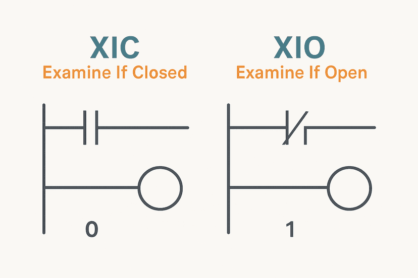
This distinction matters most when simulating XIC and XIO contact behaviour or testing normally open vs normally closed logic, where the bit state drives multiple rungs and you need it stable across many scans.
What Simulation Won't Tell You
Simulation is not a magic bullet. Here's what it misses:
- Real I/O signal quality: noise, bounce, or wiring faults that cause intermittent sensor issues won't appear.
- Actual scan cycle jitter on the target CPU under full I/O load.
- Network communication faults like PROFINET communication loss, unless you manually force the status bits.
- Analog input accuracy: raw counts from a real 4-20 mA card behave differently from a forced integer tag. Check your analog input wiring and scaling on real hardware.
- Power-up sequencing, retentive data after a power cycle, and battery-backed SRAM behaviour.
- Safety function validation: simulating E-stop logic is useful for logic checks, but you still need a full functional safety test per your safety relay wiring and circuit design.
Quick Tips From the Field
- Simulate before every major logic change, not just during initial build. A change to one rung can break a latch three rungs away.
- Create a simulation test script: a text file listing which tags to force, in what order, and what the expected outputs are. This becomes your regression test for future changes.
- If your project uses PLC scan cycle timing critically, measure the simulated scan time and compare to the target hardware spec. PC schedulers add jitter.
- For projects connecting to SCADA or HMI, run PLCSIM Advanced or Logix Emulate with a live HMI simulation to catch tag mapping errors before FAT. HMI tag linking mistakes are very common and very slow to debug on site.
- Always remove all forces before downloading to real hardware. It sounds obvious until you forget at 11 pm during commissioning.
Keep Learning
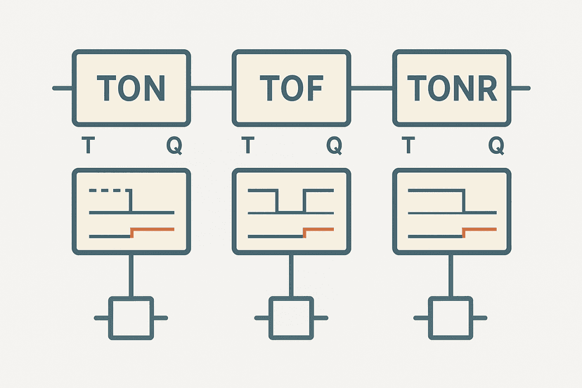
Simulation is most valuable when your ladder logic is solid to begin with. Brush up on TON, TOF and TONR timer behaviour so you know what to expect when you force inputs in simulation. For more hands-on practice, work through a complete project like the PLC bottle filling machine exercise and then simulate it step by step. If you want to go deeper on fault diagnosis after simulation, PLC I/O fault diagnosis with a multimeter covers the hardware side that simulation can't replace.
Frequently asked questions
Can I simulate ladder logic without a real PLC?
What is the difference between simulation and emulation for PLCs?
Does Studio 5000 have a built-in simulator?
Is TIA Portal PLCSIM free?
Can I simulate communication faults in ladder logic simulation?
How accurate is CODESYS simulation compared to real hardware?
Can I connect an HMI to a simulated PLC?
What ladder logic errors does simulation catch that code review misses?
Does simulating ladder logic replace a Factory Acceptance Test?
Now build it
You have just read about TON. Reading a rung and making one behave are different skills, and the second one is the job.
Flasher
Intermediateabout 15 minTwo timers chained in a loop make a lamp blink: the classic two-TON flasher used for warning beacons everywhere. Your first taste of timers driving each other.
Build this rungFree, no signup, runs in your browser. See all 16 exercises.
Was this helpful?