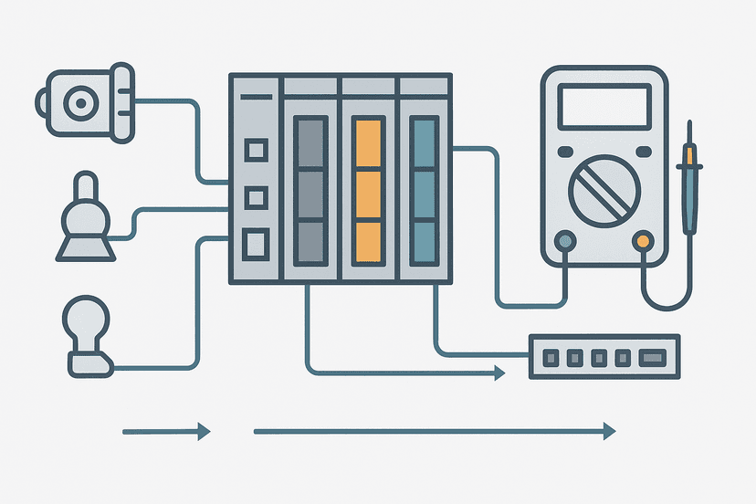
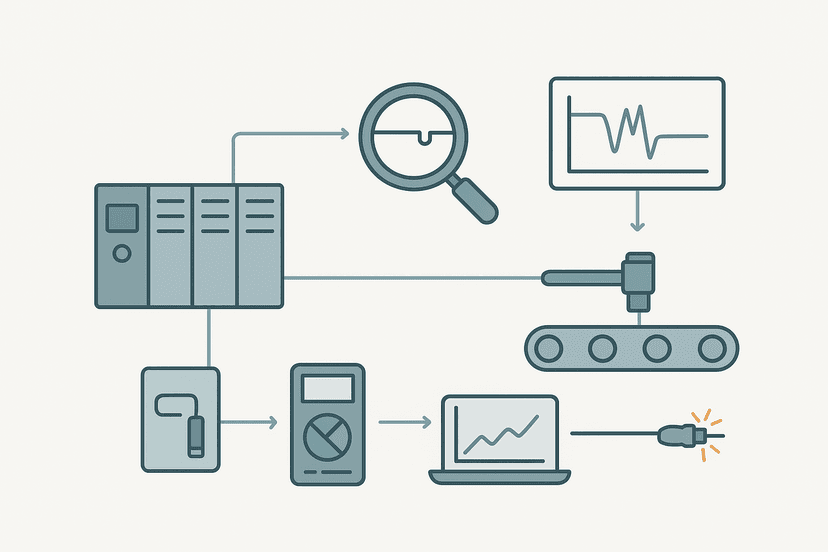
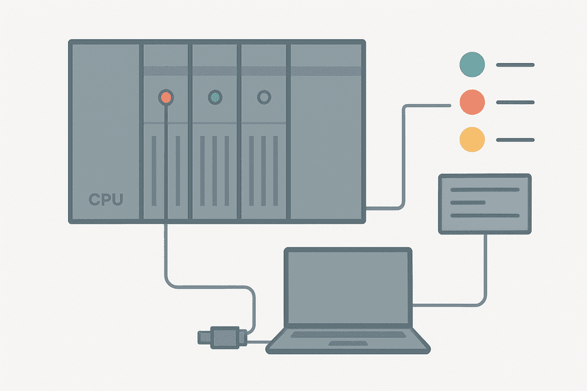
How to Test a PLC Input: Step-by-Step Guide
A PLC input that refuses to work is the most common fault call in commissioning and maintenance. The good news is that a digital input has only a handful of failure points, and you can isolate every one of them in under ten minutes with a multimeter and online monitoring software. The bad news is that people skip steps, guess wrong and waste hours replacing hardware that was fine.
How to Test a PLC Input
Testing a PLC digital input means confirming three things in order: the field device is generating the correct voltage, that voltage is arriving at the PLC input terminal, and the PLC is reading the terminal state correctly in software. Work through those three checks in sequence and you will find the fault every time. Skipping to software forcing before checking field voltage is the single most common mistake.
What You Need Before You Start
- A digital multimeter, CAT III rated, with probes that fit your terminal block style
- The panel wiring diagram for the specific input channel (do not guess which terminal is common)
- Online access to the PLC via the programming software (TIA Portal, Studio 5000, GX Works3, etc.)
- The input module datasheet so you know the ON-state voltage threshold (typically 15 V minimum for 24 VDC modules)
- A second person if the field device is in a hazardous or restricted area
Step 1: Check the Field Device Output Voltage
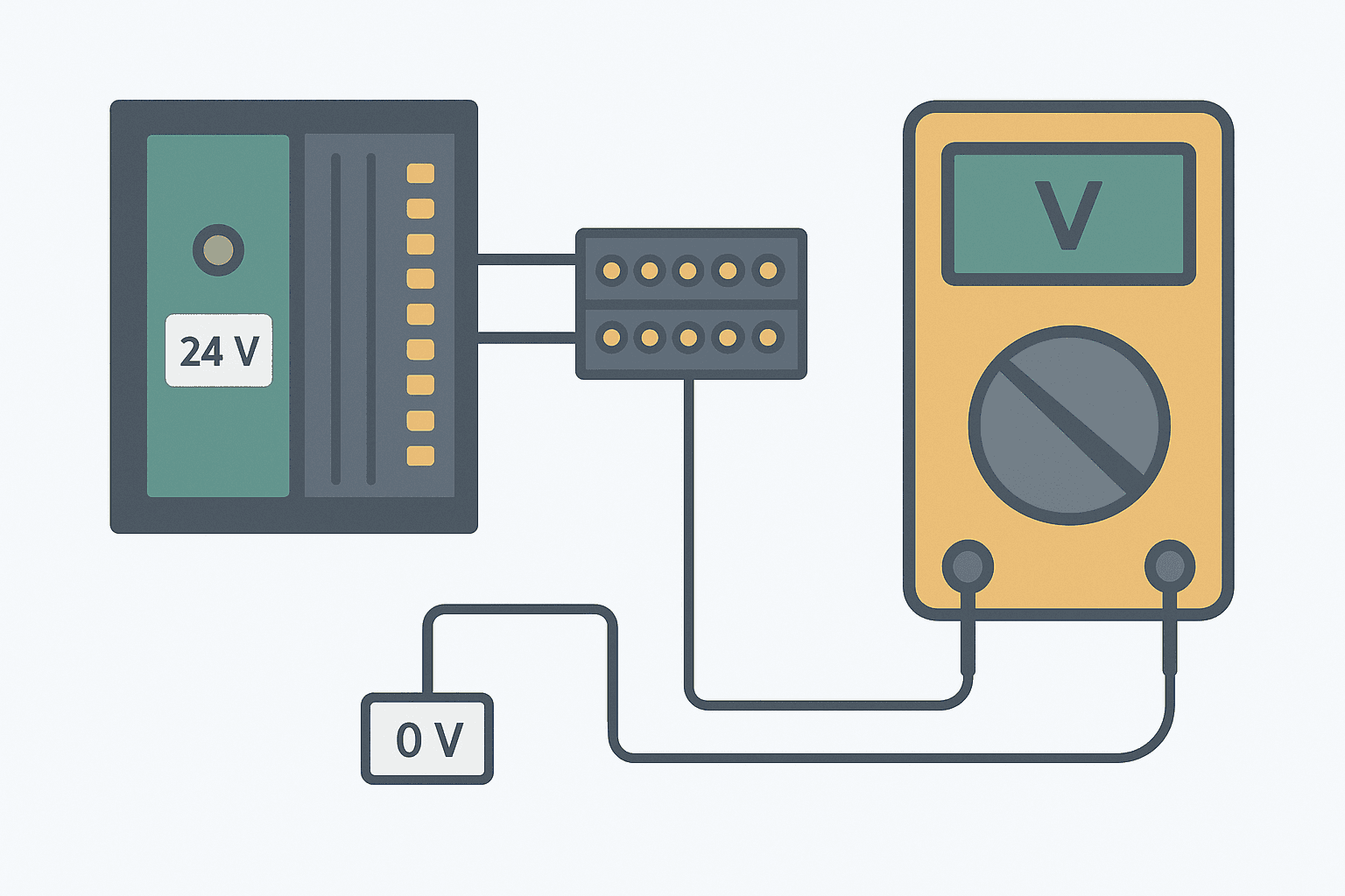
Start at the source, not at the PLC. Operate the field device (push the button, trip the limit switch, block the sensor) and measure the voltage at the device's output terminal relative to the 0 V rail. For a 24 VDC system you want to see 20 to 28 VDC when the device is active. Anything below 18 V is suspect. Below 5 V means the device is either not switching or its supply is missing.
If you are working with a 3-wire PNP or NPN sensor, the measurement method is slightly different depending on the output type. The 3-wire sensor wiring guide covers this in detail, including how to confirm the sensor's output transistor is actually switching. Get that right before moving to the PLC terminal.
Step 2: Measure Voltage at the PLC Input Terminal
With the field device active, move your multimeter probes to the PLC input terminal and the input module's common (0 V) terminal. These are labeled on the module, usually as a numbered input and a COM or M terminal. You should read the same voltage you measured at the device. If you measured 24 V at the sensor but only 8 V at the PLC terminal, you have a wiring fault: a broken conductor, a corroded terminal, a loose ferrule or a missing 0 V return.
| Voltage at PLC Terminal | Likely Cause |
|---|---|
| 20 to 28 VDC (input ON) | Correct signal, hardware is fine |
| 0 to 2 VDC (input OFF) | Correct off-state |
| 8 to 15 VDC (marginal) | Long cable, high impedance sensor, or corroded terminal |
| 24 V but bit stays OFF | Module filter time, forced-off, or bad channel |
| 0 V but device appears active | Open circuit in wiring, wrong common, blown sensor output |
One gotcha I've been caught by more than once: the input module and the field device sharing the same 24 VDC supply but using different 0 V commons that are not connected together. The device switches 24 V fine, the voltage at the PLC terminal looks correct relative to the device's 0 V, but the module's COM is on a different rail. Result: 0 V at the PLC input, no bit, confused engineer. Always confirm both supply and return are on the same common before chasing anything else.

Step 3: Confirm the Software Is Reading the Terminal
Now go online with your programming software. Navigate to the input address in question and watch the status bit in real time. Toggle the field device and the bit should follow immediately, or within the input filter time (typically 1 to 8 ms for standard digital inputs). If the voltage at the terminal is correct but the bit does not change, you have narrowed it down to three possibilities: an active force on that bit, a hardware fault on the input channel, or an incorrect address in the program.
For Rockwell Studio 5000, open the Controller Tags table and filter on the I/O alias or direct address. The tag browser will show a small F icon if the point is forced. For Siemens TIA Portal, use the Watch Table or the I/O status view inside the device diagnostics. The PLC troubleshooting with online monitoring guide has a full walkthrough for navigating these views across different platforms.
Step 4: Check for Active Forces
Forces are the silent killer of input testing. A forced-off input will read 0 in software regardless of what voltage is at the terminal. Open the I/O force table (Studio 5000: Logic menu > I/O Force Table; TIA Portal: Online > Force Table). If you see any forces active, note them, understand why they were set, and only remove them if it is safe to do so. Never assume a force was left there by accident. Someone may have forced that input off because the real device is failed and the machine needs to run.
Step 5: Test the Module Channel Itself
If you have good voltage at the terminal, no forces active, and the bit still does not move, test the channel by temporarily wiring a known-good signal directly to the input terminal. Use a jumper from the 24 VDC supply positive rail to the input terminal (through a fuse or current-limiting resistor if you want to be cautious). If the bit still does not change, the channel is likely failed and you need to swap to a spare channel or replace the module.
Before condemning a module, check the module's diagnostic LEDs and the PLC diagnostics buffer. Most modern modules flag individual channel faults. In TIA Portal, the module diagnostics tab will show channel-level faults. The PLC CPU faults guide explains how to read the diagnostic buffer, which often contains channel fault entries that point you straight at the failed hardware. And the PLC I/O fault diagnosis with a multimeter guide covers the full multimeter procedure in more depth.
Step 6: Check the Sinking vs Sourcing Wiring
If the channel is new and has never worked, not just stopped working, the most common cause is a wiring mismatch between sinking and sourcing. A PNP sensor wired to a sourcing input module, or an NPN sensor to a sinking module, will not work and could damage the sensor output transistor. The sinking vs sourcing I/O guide has the wiring diagrams you need. This is especially common when someone orders a replacement sensor of the wrong output type.
Step 7: Simulate the Input to Test Downstream Logic
Once you have confirmed the input hardware is working, you might still need to test the logic that consumes that input without the physical device present. This is where simulation comes in. Most platforms let you force an input bit ON or OFF to validate the downstream ladder rungs. If you want to test without any real hardware at all, the post on simulating ladder logic without a PLC covers the software-only options.
For programs with timer-driven logic, forcing the input ON and watching the TON or TOF timer accumulate is a quick sanity check that the rung is wired correctly and the preset is reasonable. If the timer never starts despite the input being forced ON, look upstream for an interlock contact that is still blocking the rung.
Intermittent Inputs: A Special Case
An input that drops out randomly is harder to catch than one that is simply dead. The best approach is to set up a one-shot latch in the program that captures the dropout event, or use the data logging feature in your programming software to record the bit state over time. Physically wiggling cables and connectors while watching online monitoring will often reproduce the fault immediately if the cause is a loose ferrule or cracked conductor near a flexing point.
Input filter time is also worth checking. Most modules have a configurable software filter between 1 and 20 ms. If the field device generates a very short pulse (under 5 ms), the module may filter it out entirely. Reduce the filter time or check the PLC scan cycle troubleshooting guide if you suspect the scan cycle is missing fast events. The intermittent sensor fault guide is also worth reading if you are stuck on a fault that will not reproduce on demand.
Common PLC Input Faults at a Glance
| Symptom | Most Likely Cause | First Check |
|---|---|---|
| Bit OFF, 0 V at terminal, device active | Open circuit in wiring or wrong common | Trace the conductor and check COM rail |
| Bit OFF, 24 V at terminal, no forces | Failed input channel | Jumper a known signal, swap to spare channel |
| Bit ON, nothing energized in field | Force active or simulation mode | Open force table, clear forces |
| Bit flickers randomly | Loose terminal or marginal sensor | Wiggle test, check ferrule torque |
| Bit ON but LED OFF on module | Address mismatch in program | Confirm physical channel matches tag address |
Address mismatches deserve a mention. On Siemens S7-1200, if you move a module to a different slot without updating the hardware configuration in TIA Portal, the address offsets shift and the program reads the wrong physical channel. The PLC memory and addressing guide explains how address assignment works across different platforms so you can spot this quickly.
On Rockwell ControlLogix and CompactLogix, I/O addresses are tag-based and tied to the module slot in the I/O tree, so a slot change forces a tag update too. That is actually safer, because the compile will flag the broken reference. But if someone manually edited a tag address string, the mismatch can be invisible until you go online and compare physical to logical channel by channel.
Analog Inputs Are Different
Everything above applies to discrete (on/off) inputs. Analog inputs (4-20 mA, 0-10 V) need a different approach. You check the raw count value in the program, not just a Boolean bit, and you need to know the expected engineering unit range. The PLC analog input wiring guide and the 4-20 mA scaling formula post cover the full analog testing procedure, including how to use a loop calibrator to inject a known current and verify the scaling is correct end to end.
What to Read Next
If you have confirmed the input hardware is good and the fault is in the logic itself, start with the PLC scan cycle troubleshooting guide to rule out timing issues, then look at XIC vs XIO contacts to make sure normally-open and normally-closed contact logic is correct in your rungs. For a broader diagnostic workflow that starts with the CPU status LEDs and works outward, the PLC CPU faults step-by-step guide is the logical next stop.
Frequently asked questions
What voltage should I measure at a PLC digital input?
Why does a PLC input show ON in software but nothing is energized in the field?
Can I test a PLC input without a multimeter?
What is the difference between a sinking and sourcing input when testing?
How do I test a PLC input that is intermittently dropping out?
Is it safe to force a PLC input during testing?
What causes a PLC input LED to be ON but the software bit stays OFF?
How do I test a PLC input on an S7-1200 in TIA Portal?
Now build it
You have just read about XIC and XIO. Reading a rung and making one behave are different skills, and the second one is the job.
Start / Stop Circuit
Beginnerabout 10 minThe first circuit every controls engineer learns: a motor that starts on a button press, keeps running when the button is released, and stops on a stop button, with stop always winning.
Build this rungFree, no signup, runs in your browser. See all 16 exercises.
Was this helpful?