TON, TOF and TONR Timers: What Actually Differs
Ask ten techs how a TON timer works and nine of them will get it right. Ask them how TOF behaves when the input drops and comes back before the timer finishes, or what TONR actually retains, and you'll get a lot of hesitation. These three instructions are the backbone of almost every program you'll ever write, and the differences between them are subtle enough to cause real problems on the floor.
This post covers all three: what each one does, how the internal bits behave, what resets them, and the failure modes that catch people off guard. Examples are in Rockwell Studio 5000 / Logix syntax, but the logic applies directly to Siemens TIA Portal (TP/TON/TOF), CODESYS, and virtually every IEC 61131-3 platform.
TON: Timer On-Delay
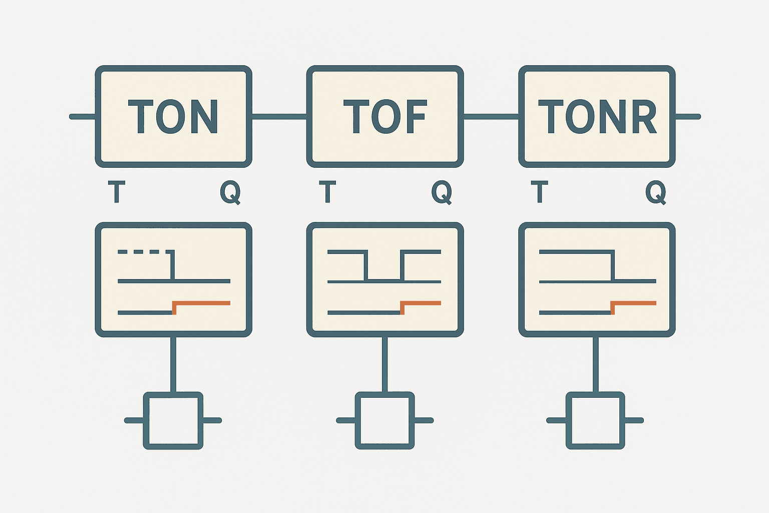
TON is the one everyone starts with. When the rung goes true, the timer accumulates. When the accumulated value (ACC) reaches the preset (PRE), the done bit (.DN) goes true. While the rung is true and the timer hasn't finished, the timer-timing bit (.TT) is also true. The moment the rung goes false, ACC resets to zero instantly, .DN drops, and .TT drops. No exceptions.
ACC goes back to zero. You'll think the timer is running, but it restarted silently. If you need accumulated time to survive a momentary dropout, TON is the wrong tool. Use TONR instead.TON presets in Studio 5000 are in milliseconds for TIMER data types. A PRE of 5000 means 5 seconds. The resolution is one PLC scan, so on a 10 ms scan you'll get plus-or-minus 10 ms accuracy. For tight timing (sub-20 ms), move to a task with a shorter period or use the high-speed counter instead.
TON timing diagram in plain terms
| Rung condition | ACC behaviour | .TT bit | .DN bit |
|---|---|---|---|
| False | Resets to 0 | False | False |
| True, ACC < PRE | Counting up | True | False |
| True, ACC >= PRE | Holds at PRE | False | True |
| Goes false while counting | Immediately resets to 0 | False | False |
TOF: Timer Off-Delay
TOF is where most people get turned around. The output .DN is true when the rung is true, and it stays true for the preset duration after the rung goes false. Read that twice. The timer is energised by the rung going false, not true.
A real use case: a cooling fan that has to keep running for 30 seconds after a motor shuts off. You wire the motor-running bit to the TOF input. The fan output comes from .DN. Motor runs, .DN is true, fan runs. Motor stops, .TT starts timing 30 seconds. When timing completes, .DN drops and the fan stops. Clean, no extra latching logic needed.
| Rung condition | ACC behaviour | .TT bit | .DN bit |
|---|---|---|---|
| True | Resets to 0 | False | True |
| Goes false, ACC < PRE | Counting up | True | True |
| False, ACC >= PRE | Holds at PRE | False | False |
| Goes true while counting | Immediately resets to 0 | False | True |
ACC resets to zero and .DN stays true. This is correct behaviour, but it surprises people the first time. The timer effectively restarts its off-delay each time the rung drops. A light blinker wired through a TOF with a short preset and a fast-cycling input will never let .DN drop if the off-delay is longer than the off-time of the pulse.TONR: Retentive Timer On-Delay
TONR accumulates time across multiple rung-true pulses. When the rung goes false, ACC holds its value instead of resetting. When the rung goes true again, counting resumes from where it stopped. The only way to reset ACC is an explicit RES instruction or writing zero to ACC directly.
Classic applications: total run-time tracking, scheduled maintenance intervals, or debouncing a noisy input where you need the signal to accumulate a total of, say, 200 ms of true state across multiple short pulses before you act on it. That last one is a technique worth putting in your toolkit. A TON would reset on every gap; TONR accumulates through them.
TIMER data types are stored in controller-scoped or program-scoped tags. By default, ACC does NOT survive a power cycle unless you put the tag in a retentive memory area or use a produced/consumed tag with persistent storage. If your maintenance-hour counter needs to survive a power outage, store ACC to a retentive integer tag on every scan, and reload it on first scan after startup. Don't assume TONR handles this automatically.Side-by-side comparison
| Feature | TON | TOF | TONR |
|---|---|---|---|
| Starts timing when... | Rung goes TRUE | Rung goes FALSE | Rung goes TRUE |
| .DN true when... | ACC >= PRE (rung still true) | Rung true OR timing after false | ACC >= PRE (rung can be either) |
| ACC on rung false | Resets to 0 | Counts up (timing) | Holds last value |
| Requires explicit reset | No | No | Yes (RES instruction) |
| Survives power cycle (Logix) | No (default) | No (default) | No (default, same caveat) |
| Typical use | Delay before action | Delay after action stops | Accumulated time, debounce |
TON, TOF and TONR in IEC 61131-3 platforms
In CODESYS and TIA Portal, the naming and pin layout differ slightly. Siemens uses TON, TOF, and TONR in SCL/ST, with IN, PT (preset time), Q (done), and ET (elapsed time) as the standard pins. The PT value is a TIME literal like T#5S rather than an integer in milliseconds. CODESYS follows the same IEC convention. The underlying behaviour is identical to what's described above. The RES for a retentive timer in CODESYS is done by setting IN := FALSE and R := TRUE on the RTON block.
One Siemens-specific gotcha: in TIA Portal, if you place a TON/TOF in an FB and declare the timer as a local static variable, it retains its state between calls as expected. But if you declare it as a temp variable, it resets every scan. Seen more than one programmer burn an afternoon on that.
Ladder example: TONR for equipment run-hour tracking
Here's a practical TONR pattern. A pump runs intermittently. You want to track total run time in minutes and trigger a maintenance flag at 500 hours. The TONR accumulates milliseconds while the pump is running. Every time ACC hits 60,000 ms (one minute), a one-shot increments a run-minute counter and resets the TONR. The counter drives the maintenance alarm. This avoids floating-point and gives you clean integer minutes.
TONR Run-Hour Accumulator with Maintenance Alarm (Studio 5000). Ladder logic (4 rungs): Rung 0: examine if Pump1_Running is on (XIC), then TONR on Pump1_RunTimer. Rung 1: examine if Pump1_RunTimer.DN is on (XIC), then examine if RunTimer_MinOS is on (XIC), then either CTU on Pump1_RunMinutes, then either RES on Pump1_RunTimer. Rung 2: CMP on Pump1_RunMinutes.ACC >= 30000, then latch output Pump1_Maint_Due (OTL). Rung 3: examine if Pump1_Maint_Due is on (XIC), then examine if HMI_MaintAck is on (XIC), then examine if HMI_MaintReset is on (XIC), then unlatch output Pump1_Maint_Due (OTU), then either RES on Pump1_RunMinutes. Rung 1: TONR accumulates pump run time in ms. Rung 2: when the 60-second mark is reached, a one-shot fires, the run-minute CTU increments by 1, and the TONR resets to start the next minute. Rung 3: when run minutes exceed 30,000 (500 hours), the maintenance latch sets. Rung 4: operator acknowledges and resets the counter from HMI. The pattern handles intermittent pump operation correctly because TONR holds ACC across off periods.
Common mistakes and how to avoid them
- Using TON to debounce a chattering sensor. If the sensor bounces false for even one scan, ACC resets. Use TONR and a RES on a clean-signal confirmation instead.
- Expecting TOF to delay the ON transition. It doesn't. TOF delays the OFF. If you want both an on-delay and an off-delay, you need two timers: a TON for the leading edge and a TOF driven by TON.DN for the trailing edge.
- Sharing a timer tag across multiple rungs. Each TON/TOF/TONR tag should only be driven by one rung. Two rungs writing to the same timer instance will fight each other on every scan. Use separate timer tags.
- Setting PRE from an HMI DINT and forgetting the units. If your HMI sends seconds and your TON expects milliseconds, you'll get a 1000x error. Define the engineering unit conversion at one place and document it.
- Assuming TONR survives a power cycle. It won't, by default, in Logix. Back up ACC to a retentive tag if the value matters across restarts.
- Forgetting that .TT and .DN are mutually exclusive in TON. When DN is true, TT is false. You can't use TT as a 'still running' indicator once the timer has finished. Use XIO(Timer.DN) if you need 'running but not done'.
Structured text equivalents
If you're working in structured text, the Logix equivalents look like function calls rather than instructions on a rung. You call the timer in every scan where its enable condition is true, which mirrors the rung-continuity model.
// TON: start after Gate_Closed is true for 2 seconds
IF Gate_Closed THEN
    TON(Gate_Delay_Timer, 2000, 0);
ELSE
    Gate_Delay_Timer.ACC := 0;  // manual reset if rung-false behaviour needed
END_IF;
Conveyor_Enable := Gate_Delay_Timer.DN;

// TOF: keep exhaust fan on for 30 s after motor stops
TOF(Fan_Purge_Timer, 30000, 0);  // enable = Motor_Running
Fan_Purge_Timer.TimerEnable := Motor_Running;
Exhaust_Fan := Fan_Purge_Timer.DN;

// TONR: accumulate press cycle time
IF Press_Cycling THEN
    TONR(Press_CycleTimer, 0, 0);  // PRE=0 means free-running accumulator; check .ACC
END_IF;
IF HMI_ResetCycleTimer THEN
    Press_CycleTimer.ACC := 0;
    Press_CycleTimer.DN  := 0;
END_IF;TON() with the enable condition inside the IF block is functionally equivalent to having the condition on the left side of the ladder rung. The timer only accumulates while the function is being called with a true condition. If you skip the call entirely (no ELSE branch that resets), ACC freezes rather than resets, which can accidentally mimic TONR behaviour. Be explicit about your reset logic.If you're also working with counters alongside timers, the PLC Counter Instructions: CTU, CTD and CTUD Explained post covers the matching counter mechanics in the same level of detail, including the CTUD bidirectional counter and reset behaviour.
Picking the right timer for the job
A quick decision tree. Do you need to delay an action until a condition has been continuously true for a set time? Use TON. Do you need to keep an output active for a set time after a condition goes away? Use TOF. Do you need to accumulate time across multiple on/off cycles, or build a run-hour meter? Use TONR with an explicit RES. If you're unsure, TON is the safe default because its behaviour is predictable and it self-resets without extra logic.
One more thing: don't be tempted to simulate TONR with a TON and a latch bit. It works until someone resets the latch at the wrong moment, or until a power cycle leaves the latch set. The dedicated TONR instruction is cleaner, better documented in the code, and less likely to confuse the next engineer on the job.
Frequently asked questions
What is the difference between TON and TONR in Studio 5000?
How does the TOF timer work in ladder logic?
Does TONR retain its value through a PLC power cycle?
Can you use the same timer tag in multiple rungs?
What is the .TT bit on a PLC timer and when should you use it?
How do TON, TOF and TONR map to IEC 61131-3 standard timer blocks?
Now build it
You have just read about RTO and RES. Reading a rung and making one behave are different skills, and the second one is the job.
Service Interval (RTO + RES)
Advancedabout 18 minTotal ACCUMULATED run-time, across any number of stop/starts, must trigger a service lamp at 3 seconds. A normal TON forgets on every stop; the retentive RTO remembers until you RES it.
Build this rungFree, no signup, runs in your browser. See all 16 exercises.
Was this helpful?