PLC Counter Instructions: CTU, CTD and CTUD Explained
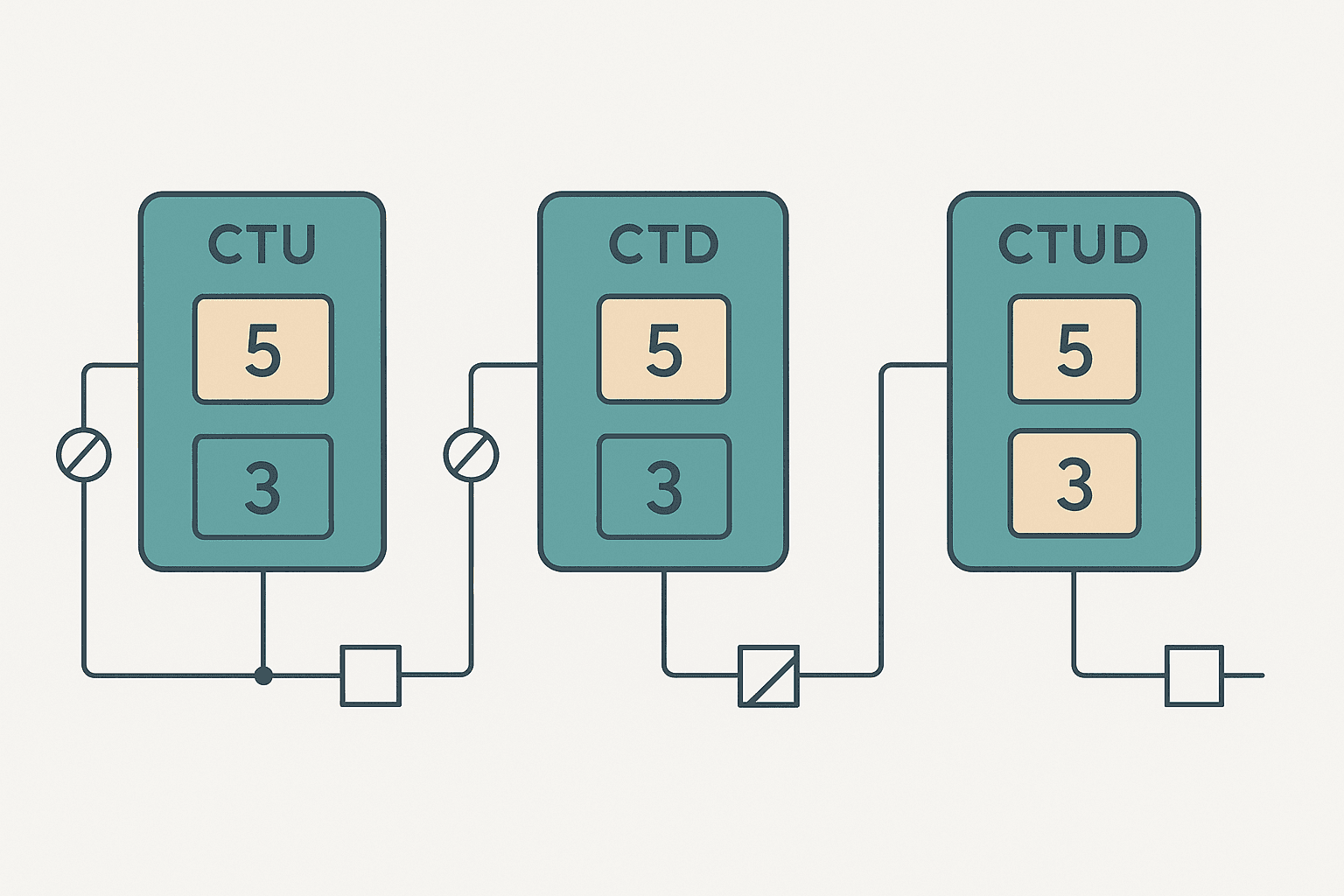
Counters are one of those instructions that look dead simple until you try to use them in a real program and something goes wrong. The accumulated count won't reset when you expect it to, the done bit fires one scan too late, or you mix up which edge actually increments the count. This post cuts through that confusion. We'll cover CTU, CTD and CTUD, explain the internal bits and what drives them, and show you exactly how the behaviour differs between IEC 61131-3 compliant platforms and Rockwell's Logix family.
What a PLC Counter Actually Does
A counter instruction tracks a transition, specifically a rising edge on its count input, and increments or decrements an internal integer register called the accumulated value (ACC or .ACC). You compare that accumulated value against a preset value (PRE or .PRE) to drive output bits. That's the whole mechanism. Everything else, overflow behaviour, reset logic, the done bit, is detail layered on top.
One critical thing to nail down before anything else: counters count edges, not levels. If your count input is continuously ON for 50 scans, the counter increments exactly once, on the first scan where it sees the OFF-to-ON transition. Get that wrong and you'll spend an afternoon wondering why your counter only ever reads 1.
CTU: Count Up Instruction
CTU is the most common counter in any program. Each rising edge on the CU input increments ACC by 1. When ACC reaches PRE, the Done bit (DN or .DN) sets. On Rockwell Logix, ACC keeps climbing past PRE until it hits the 32-bit signed integer ceiling of 2,147,483,647, then rolls over to the most negative value. On IEC platforms like CODESYS or TwinCAT, the behaviour above PRE depends on the data type you assign to CV: if you use WORD it wraps at 65,535; if you use INT it wraps at 32,767.
| Bit / Output | Name | When it sets |
|---|---|---|
| .DN / Q | Done | ACC >= PRE |
| .CU | Count Up Enable | Mirrors the CU input rung condition |
| .OV | Overflow (Logix only) | ACC has wrapped past max positive integer |
| .CD | Count Down Enable (CTUD only) | Mirrors the CD input rung condition |
CTD: Count Down Instruction
CTD does the mirror image: each rising edge on its CD input decrements ACC by 1. The Done bit sets when ACC falls to zero or below. In Logix, CTD and CTU share the same counter data structure (COUNTER), so you can have a CTU and a CTD both pointing at the same tag. That's how bidirectional counting worked in the old PLC-5 era before CTUD existed. It still works in Logix 5000, but it's messier than using CTUD.
CTD alone is less common in practice. The main use case is loading PRE with a target quantity at the start of a batch, then counting down as items are consumed or dispensed, so the remaining count reads naturally on an HMI without any subtraction math. Operators find "125 remaining" more intuitive than "375 of 500 done".
CTUD: Bidirectional Counter
CTUD gives you separate CU and CD inputs on a single function block. It's the IEC 61131-3 standard counter for bidirectional counting, and it's the natural choice in CODESYS, TwinCAT, Sysmac, and Mitsubishi GX Works3 (where it's called UDCNT). Rockwell doesn't have a native CTUD instruction in Studio 5000, but you get the same result by pointing a CTU and a CTD at the same COUNTER tag, which I'll show below.
A good real-world application for CTUD: tracking how many parts are currently inside a buffer zone on a conveyor. A sensor at the entry increments the count; a sensor at the exit decrements it. The buffer-full alarm fires when the count hits your capacity limit; the buffer-empty alarm fires when it reaches zero. Clean, readable, and the count is always the live occupancy number.
Preset vs Accumulated: Getting the Numbers Right
PRE is what you set; ACC is what the counter measures. The Done bit compares them. A few things to keep in mind:
- PRE can be a constant or a tag. If you drive PRE from an HMI integer tag, operators can change the batch target at runtime without touching the program. Just make sure you validate the range so no one enters 0 or a negative number.
- ACC is writable. You can MOV a value into ACC to pre-load the counter, useful for resuming after a power cycle if you've stored ACC in retentive memory.
- In Logix, both PRE and ACC are DINT (32-bit signed). In IEC platforms they're usually INT (16-bit signed, range -32,768 to 32,767) or UINT (0 to 65,535) depending on what you declare. Trying to count to 50,000 with an INT type will wrap and confuse you.
- The DN bit in CTU does NOT reset automatically when ACC drops back below PRE. You have to RES the counter or the DN bit stays set. This surprises a lot of beginners.
Ladder Example: Bidirectional Buffer Counter (Studio 5000)
Here's a practical bidirectional counter using a CTU and CTD sharing the same COUNTER tag called Buffer_Count. The entry sensor increments, the exit sensor decrements, and the buffer-full output fires when ACC reaches the preset of 10 parts.
Bidirectional Buffer Zone Counter (Studio 5000 / Logix). Ladder logic (4 rungs): Rung 0: examine if Entry_Sensor is on (XIC), then CTU on Buffer_Count. Rung 1: examine if Exit_Sensor is on (XIC), then CTD on Buffer_Count. Rung 2: examine if Buffer_Count.DN is on (XIC), then energize output Buffer_Full_Alarm (OTE). Rung 3: examine if Buffer_Empty_Btn is on (XIC), then RES on Buffer_Count. Rung 1: Rising edge on Entry_Sensor increments Buffer_Count.ACC. Rung 2: Rising edge on Exit_Sensor decrements Buffer_Count.ACC. Both CTU and CTD share the same COUNTER tag so ACC reflects net occupancy. Rung 3: Buffer_Full_Alarm fires when ACC reaches PRE of 10. Rung 4: Operator reset button clears ACC and all bits.
The diagram above evaluates one scan. Run these exact rungs on a real scan cycle to watch the latching and the timers behave.
Run this in the simulatorBuffer_Count is good. CTU_1 tells the next engineer nothing. The instruction type is already visible in the ladder; you don't need to encode it in the tag name.IEC 61131-3 Structured Text Equivalent
If you're working in CODESYS, TwinCAT or Sysmac Studio and prefer Structured Text, the same bidirectional logic looks like this. The CTUD function block has separate Q_U and Q_D outputs for the up-done and down-done conditions respectively.
// Declare in variable section:
// Buffer_Count : CTUD;
// Buffer_Full  : BOOL;
// Buffer_Empty : BOOL;

// Call the function block every scan
Buffer_Count(
    CU := Entry_Sensor,     // rising edge increments CV
    CD := Exit_Sensor,      // rising edge decrements CV
    R  := Reset_Buffer_Btn, // synchronous reset, CV -> 0
    LD := FALSE,            // no load function used here
    PV := 10                // preset / upper limit
);

Buffer_Full  := Buffer_Count.Q_U;  // TRUE when CV >= PV
Buffer_Empty := Buffer_Count.Q_D;  // TRUE when CV <= 0
Notice the R input is a level signal, not an edge. As long as Reset_Buffer_Btn is TRUE, CV stays at 0. The moment it goes FALSE the counter is live again. This is different from Logix where the RES instruction only acts on the scan where its rung is true.
Common Gotchas with PLC Counters
Counting mechanical bounces
A mechanical limit switch or push-button can bounce 5 to 20 times in the first millisecond after contact. If your scan cycle is fast (under 5 ms) and the input filter on your I/O module is set low, the counter can increment 2 or 3 counts per physical event. The fix is usually the hardware input filter on the module, typically settable to 1 ms, 2 ms or 10 ms, not a software debounce timer. Check the module datasheet. On a 1769-IQ16 for example, the default filter is 1 ms and you can push it to 10 ms via module properties in Studio 5000.
Forgetting that ACC survives a minor fault
In Logix, counter tags live in the controller's data table. A recoverable fault that doesn't clear memory will leave ACC at whatever value it held. If your machine restarts after a fault mid-batch, the counter might read 47 when the real count is 0. Either RES the counter as part of your fault recovery routine, or save ACC to a retentive DINT tag before a controlled stop so you can restore it correctly.
Using .DN as a permissive without resetting
Here's one that I've seen bite junior engineers repeatedly. They use XIC(My_Counter.DN) as a permissive in a rung, expecting it to pulse once when the count is reached. But .DN stays set until you RES the counter. So the permissive stays TRUE every scan after the target is hit. If you need a one-shot, use an OSR (one-shot rising) off the .DN bit, exactly like the batch counter example in the bottle filling project. That fires a single-scan pulse which you can then use to trigger a state transition or latch an output.
Preset of zero
If PRE is 0, the DN bit sets immediately when the counter is instantiated, before you even count anything. This happens because ACC (0) >= PRE (0) is true from the start. If you let an operator enter the preset from an HMI, validate that it's at least 1. A zero preset will make your batch end before it starts and you'll spend 20 minutes convinced the logic is wrong.
Vendor Differences at a Glance
| Platform | Up Counter | Down Counter | Bidirectional | Reset Method | Max Count (default type) |
|---|---|---|---|---|---|
| Studio 5000 / Logix | CTU | CTD | CTU + CTD on same tag | RES instruction (edge) | 2,147,483,647 (DINT) |
| TIA Portal S7-1200/1500 | CTU (IEC) | CTD (IEC) | CTUD (IEC) | R input pin (level) | 32,767 (INT) or 2,147,483,647 (DINT) |
| CODESYS 3.x | CTU | CTD | CTUD | R input pin (level) | 32,767 (INT) default |
| Omron Sysmac NJ/NX | CTU | CTD | CTUD | R input pin (level) | 2,147,483,647 (DINT) |
| Mitsubishi GX Works3 (FX5) | C0-C199 | DECO/UDCNT | UDCNT | RST instruction | 32,767 (16-bit) or 2,147,483,647 (32-bit) |
| Beckhoff TwinCAT 3 | CTU | CTD | CTUD | R input pin (level) | 32,767 (INT) default |
Where Counters Fit in Real Applications
Beyond the obvious batch counting, counters show up in more places than you'd expect:
- Maintenance triggers. Count motor starts or valve cycles. When ACC hits 10,000, set a maintenance-due flag. Reset manually after the service is done.
- Fault frequency monitoring. Count how many times a sensor drops out per shift. If it exceeds 5, flag an investigation. You can see this pattern in intermittent fault diagnosis workflows.
- Sequencer step indexing. Increment a step counter on each rising edge of a step-complete signal. Use the ACC value in a CASE statement to select the next action. Cleaner than a tower of latching rungs.
- Product variant selection. Count items processed on a mixed-product line. When the count for one variant is done, advance to the next recipe index.
- Encoder pulse counting. On low-speed applications without a dedicated HSC module, you can use a CTU to count encoder pulses directly from a standard digital input, as long as the pulse frequency stays well below your scan rate divided by 2.
For the encoder application, be honest about your scan cycle. A 10 ms scan gives you a maximum reliable input frequency of around 50 Hz, which is 50 pulses per second. Anything faster needs a high-speed counter (HSC) module or the on-board HSC inputs available on most compact PLCs. Trying to count 500 Hz pulses through a standard input and a 10 ms scan will drop most of them. This is the same edge-detection limit that applies to any fast digital input, and it's covered in more detail in the PLC memory and addressing post where scan-cycle timing is discussed.
Quick Checklist Before You Use a Counter
- Is your input truly an edge signal, or a level? If it's a level, add a one-shot (OSR/OSF) before the counter input.
- What data type does the counter use on your platform? Will it overflow before you reach your maximum expected count?
- How and when does the counter reset? Is that reset manual, automatic on Done, or tied to a machine state transition?
- If PRE comes from an HMI tag, have you validated the minimum and maximum allowable values?
- Do you need the count to survive a power cycle? If yes, use retentive memory or back up ACC explicitly.
- Is your input frequency low enough for standard digital I/O, or do you need a high-speed counter module?
Frequently asked questions
What is the difference between CTU and CTD in PLC programming?
Why does my PLC counter keep counting past the preset value?
How do I reset a CTU counter in Studio 5000 (Logix)?
What is the maximum count value for a PLC counter?
Can a PLC counter count high-speed pulses from an encoder?
What is CTUD and when should I use it?
Now build it
You have just read about CTU and CTD and CTUD. Reading a rung and making one behave are different skills, and the second one is the job.
Batch Counter (CTU + RES)
Intermediateabout 15 minCount parts passing a sensor; after 4 parts the batch is done and a lamp turns on. A reset button starts the next batch. Counters count RUNG EDGES: a part sitting on the sensor counts once, not forever.
Build this rungFree, no signup, runs in your browser. See all 16 exercises.
Was this helpful?