XIC vs XIO: Ladder Logic Contacts Explained
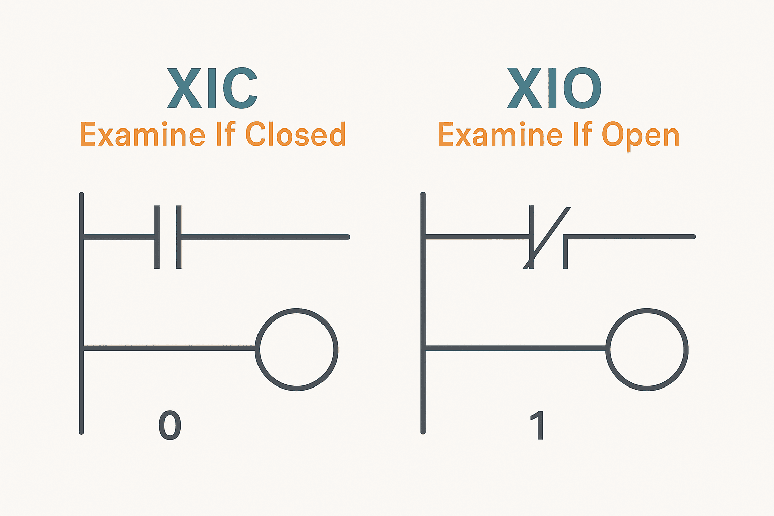
XIC and XIO are the first two instructions you encounter in Allen-Bradley ladder logic, and they are also the source of more commissioning head-scratching than almost anything else. They look simple. Two vertical bars, or two vertical bars with a slash. But the mental model that connects the symbol to the bit value to the physical wiring trips up engineers at every level, from first-week students to experienced techs moving from a different vendor platform.
What Is the Difference Between XIC and XIO?
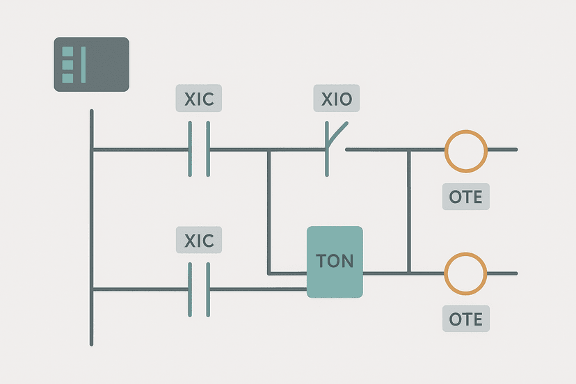
XIC (Examine If Closed) evaluates to TRUE and passes power when the bit it references is 1. XIO (Examine If Open) evaluates to TRUE and passes power when the bit it references is 0. They are logical inverses. XIC is the ladder equivalent of a normally open relay contact; XIO mirrors a normally closed contact. Both instructions read the current value of a single BOOL tag in the PLC's data table, and they do that read fresh on every scan.
| Instruction | Full Name | Passes power when bit is... | Relay equivalent |
|---|---|---|---|
| XIC | Examine If Closed | 1 (TRUE) | Normally Open (NO) |
| XIO | Examine If Open | 0 (FALSE) | Normally Closed (NC) |
How the PLC Evaluates Each Instruction
During the input scan, the processor copies physical terminal states into the input image table. During the logic scan, XIC and XIO simply look at the stored bit. Neither instruction cares whether the bit came from a physical wire, an internal flag, a timer done bit, or a counter overflow bit. The only question is: is the bit a 1 or a 0 right now?
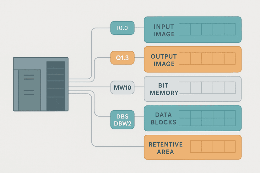
This is worth internalising. If you put an XIC on Conveyor_Run (an internal BOOL output), you are checking whether the conveyor output coil is currently energised. That is a perfectly valid interlock. Understanding PLC memory and addressing helps you see that all these bit addresses live in the same flat data table regardless of type.
XIC in Practice: When to Use It
Use XIC whenever you need to confirm that something is active or ON before taking an action. Classic examples:
- Start pushbutton (momentary, wired NO): bit goes 1 when pressed, XIC fires once
- Proximity sensor confirmation: part-in-position bit must be 1 before a fill valve opens
- Seal-in latch: XIC on the output coil tag itself to hold the rung TRUE after the start button releases
- Timer done bit:
XIC(Fill_Timer.DN)to advance a step once timing is complete - Counter done bit:
XIC(Part_Count.DN)to trigger an end-of-batch action
If you are reviewing ladder logic interview questions, XIC on a timer's .DN bit is almost guaranteed to come up. It is the most common contact type in any real program.
XIO in Practice: When to Use It
XIO is your interlock and inhibit instruction. Use it when an output must stay OFF while something else is active. Common applications:
- Stop pushbutton (wired NC, bit normally 1): XIO evaluates FALSE when the stop is pressed, dropping the rung
- Fault latch: XIO on a fault bit blocks a start command until the fault is cleared
- Interlock: XIO on an arm-extended limit switch prevents a second cylinder from firing while the first is out
- Mode inhibit: XIO on a 'Machine_Running' bit blocks a recipe-load command during production
- Timer not-done: XIO on
Purge_Timer.TTto hold a bypass open only while the timer is still timing
XIO(Stop_PB) in the rung: the XIO is TRUE (rung passes) while the bit is 1 (button not pressed). When the operator presses stop, the NC contact opens, the bit drops to 0, and XIO becomes FALSE, cutting power to the output. If you wire a stop as NO and use XIO, you get the opposite behaviour. This is the single most common wiring-versus-logic mismatch on a first commissioning. Check the physical wiring, then decide which instruction makes the rung fail-safe.The Bit Value Is Everything: Separating Wiring from Logic
This is the part that genuinely confuses people. The PLC does not know whether a physical device is normally open or normally closed. It only sees the bit. Whether that bit is a 1 or 0 depends on the wiring and the device type.
Take a 3-wire PNP proximity sensor. When a metal target is present, the PNP sensor sources current to the input, the input energises, and the bit goes to 1. A 3-wire NPN sensor does the same thing electrically but with the current path reversed. The sinking vs sourcing I/O wiring determines which of those two sensor types works with your module. But in both cases, once the bit is in the image table, XIC and XIO behave identically. The full picture for 3-wire sensors is in the PNP vs NPN wiring guide.
Safety-critical inputs add another layer. An E-stop button is always wired NC to the input, so the bit is 1 during normal operation. You use XIO on that bit so the rung drops power the instant the button is pressed. This is a fail-safe design: a broken wire also drives the bit to 0 and stops the machine. The emergency stop circuit wiring guide covers the hardware side, but your ladder logic must be consistent with it.
Series, Parallel and Mixed Contact Rungs
Contacts in series are AND logic: every contact must be TRUE for the rung to pass. Contacts in parallel branches are OR logic: any one TRUE branch is enough. You can freely mix XIC and XIO on the same rung.
A typical start circuit: [XIC(Start_PB) parallel with XIC(Motor_Run)] series XIO(Stop_PB) series XIO(Overload_Fault) -> OTE(Motor_Run). The seal-in uses XIC on the output tag itself. The stop and overload use XIO because both conditions hold the bit at 1 during normal run, and go to 0 to stop the machine. If you have worked through the PLC counter instructions or TON, TOF and TONR timer differences, you will have seen XIC and XIO in exactly those rung structures.
A Fresh Ladder Example: Conveyor Divert Gate with XIC and XIO
Here is a rung that is not the usual start/stop motor. A divert gate on a conveyor should extend only when three conditions are all met: the conveyor is running, the vision system has flagged a reject, and the gate is not already in a fault state. The gate must retract automatically once the reject timer times out.
Conveyor Divert Gate: Extend on Reject, Retract on Timer Done. Ladder logic (7 rungs): Rung 0: examine if Conveyor_Running is on (XIC), then examine if Vision_RejectFlag is on (XIC), then examine if Gate_FaultLatch is off (XIO), then latch output Gate_Extend_Cmd (OTL). Rung 1: examine if Gate_Extend_Cmd is on (XIC), then TON on Gate_Retract_Timer. Rung 2: examine if Gate_Retract_Timer.DN is on (XIC), then unlatch output Gate_Extend_Cmd (OTU), then either RES on Gate_Retract_Timer, then either unlatch output Vision_RejectFlag (OTU). Rung 3: examine if Gate_Extend_Cmd is on (XIC), then energize output Gate_Sol_Out (OTE). Rung 4: examine if Gate_Extend_Cmd is on (XIC), then examine if Gate_ExtendLS is off (XIO), then TON on Gate_Extend_Timeout. Rung 5: examine if Gate_Extend_Timeout.DN is on (XIC), then examine if Gate_Fault_OS is on (XIC), then latch output Gate_FaultLatch (OTL). Rung 6: examine if Gate_FaultLatch is on (XIC), then examine if HMI_GateFaultAck is on (XIC), then examine if Gate_Extend_Cmd is off (XIO), then unlatch output Gate_FaultLatch (OTU). Rung 1: XIC on Conveyor_Running and Vision_RejectFlag (both must be 1), XIO on Gate_FaultLatch (must be 0, i.e. no fault active), latches Gate_Extend_Cmd ON. Rung 2: starts a 500 ms retract timer while the gate is commanded out. Rung 3: when the timer done bit fires, unlatch the gate command, reset the timer, and clear the reject flag. Rung 4: drives the physical solenoid output from the latched bit. Rungs 5-6: fault detection if the extend limit switch does not confirm within 2 seconds. Rung 7: operator ack clears the fault latch only when the gate is no longer commanded.
The diagram above evaluates one scan. Run these exact rungs on a real scan cycle to watch the latching and the timers behave.
Run this in the simulatorNotice how every safety interlock uses XIO: the fault latch and the fault ack both require their respective bits to be 0 (inactive) before allowing the controlled action. That is the pattern you will see repeated across every well-written Logix program. For a bigger version of this pattern in a real machine context, the PLC bottle filling machine project shows it applied across a full sequence.
XIC vs XIO in Other IEC 61131-3 Languages
XIC and XIO are Rockwell-specific names. Other vendors use the same concept under different labels. In Siemens TIA Portal, the ladder contacts are simply called Normally Open (NO) and Normally Closed (NC), with the same relay-symbol appearance. In CODESYS and IEC 61131-3 standard ladder, the symbols are identical but the contact types are described as 'contact' and 'negated contact.' The underlying logic is the same: one passes on bit = 1, the other passes on bit = 0.
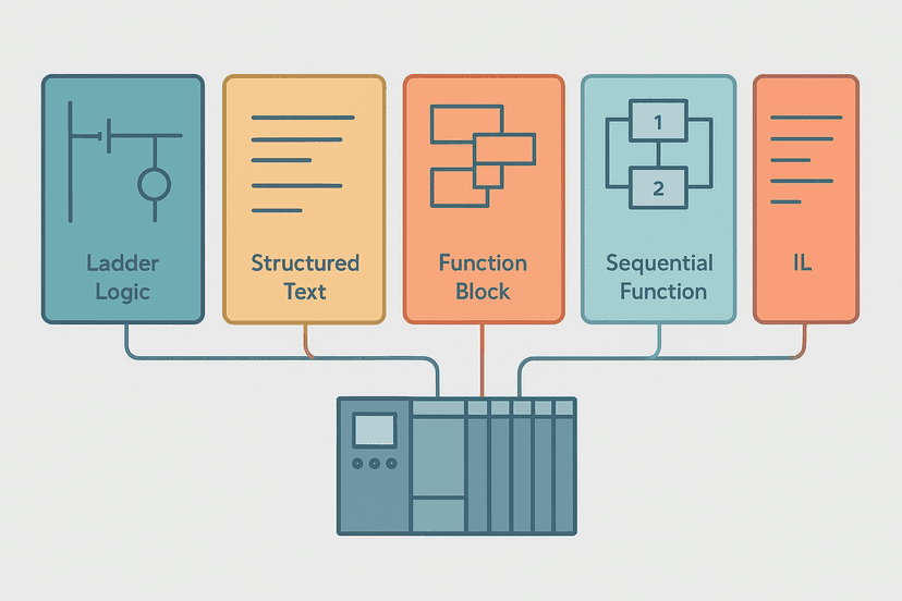
If you are moving from Siemens to Rockwell, the mental shift is just learning the new names. The 5 types of PLC programming languages article covers where ladder sits among structured text, function block, and the rest. And if you want to see how Siemens handles the equivalent in a real project, the S7-1200 first program guide walks through the TIA Portal environment.
Troubleshooting XIC and XIO Contacts Online
Studio 5000 shows a live power flow highlight when you go online. A contact that is passing power is shown in green (or highlighted, depending on your colour theme). If an XIC contact is not highlighted when you expect it to be, the referenced bit is 0. If an XIO contact is not highlighted when you expect it to be, the referenced bit is 1.
The fastest debug path: hover over the tag name on the contact to see the live bit value in the tooltip, or open the tag browser and watch the value column update in real time. If the bit is wrong, trace it back, either to the physical input via PLC I/O fault diagnosis with a multimeter, or to the logic that drives it if it is an internal bit. The PLC troubleshooting with online monitoring guide goes deeper on this workflow.
Common Mistakes With XIC and XIO
- Using XIC on a stop button wired NC. The bit is 1 at rest. XIC passes power, which is fine until you think through what happens on a wire break: the bit drops to 0, XIC goes FALSE, and the machine stops. That is actually safe behaviour. But if you intended the stop to only kill power when pressed, you need XIO.
- Using XIO on a start button. Start buttons are typically wired NO. The bit is 0 at rest. XIO would pass power constantly and trigger the start immediately on powerup. This is almost never what you want.
- Forgetting that output bits can be read by XIC/XIO. Placing XIC on an OTE output tag in the same program creates a seal-in or interlock based on the output state. This is intentional in motor starters but can create unintended latching if used carelessly.
- Confusing the physical device type with the instruction type. A NC limit switch wired to a sourcing input drives the bit to 1 when the switch is closed (target present). Whether you use XIC or XIO in logic is a separate decision based on what you want the rung to do, not on whether the switch itself is NO or NC.
- Scan-cycle timing on fast inputs. A very short pulse from a proximity sensor may only be 1 for one scan. If your XIC misses it, the rung never fires. The input pulse stretcher pattern in the PLC scan cycle problems guide addresses exactly this.
Keep Learning
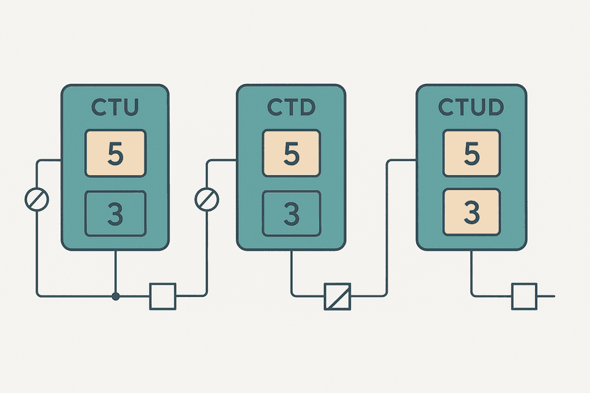
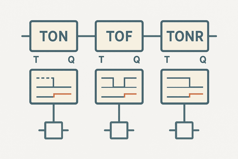
Now that XIC and XIO are clear, the natural next step is understanding the output instructions they drive: OTE, OTL and OTU. Then move on to how timer done bits and counter done bits feed back into contacts, which is where TON, TOF and TONR timers and CTU, CTD and CTUD counters become essential reading. If you are preparing for an interview, the ladder logic interview questions post covers XIC, XIO and a lot more in a format that mirrors what hiring managers actually ask.
Frequently asked questions
What does XIC mean in ladder logic?
What does XIO mean in ladder logic?
What is the difference between XIC and XIO in Allen-Bradley PLCs?
Does XIO mean the physical contact is normally closed?
Can you use XIC and XIO on internal bits, not just physical inputs?
Why does my XIO contact stay FALSE even though the physical device is open?
How do XIC and XIO appear in the Studio 5000 symbol?
Is XIC the same as a normally open contact?
Can XIC and XIO be used in series on the same rung?
Now build it
You have just read about XIO and XIC and OTE. Reading a rung and making one behave are different skills, and the second one is the job.
Start / Stop Circuit
Beginnerabout 10 minThe first circuit every controls engineer learns: a motor that starts on a button press, keeps running when the button is released, and stops on a stop button, with stop always winning.
Build this rungFree, no signup, runs in your browser. See all 16 exercises.
Was this helpful?