S7-1200 First Program in TIA Portal: Step by Step
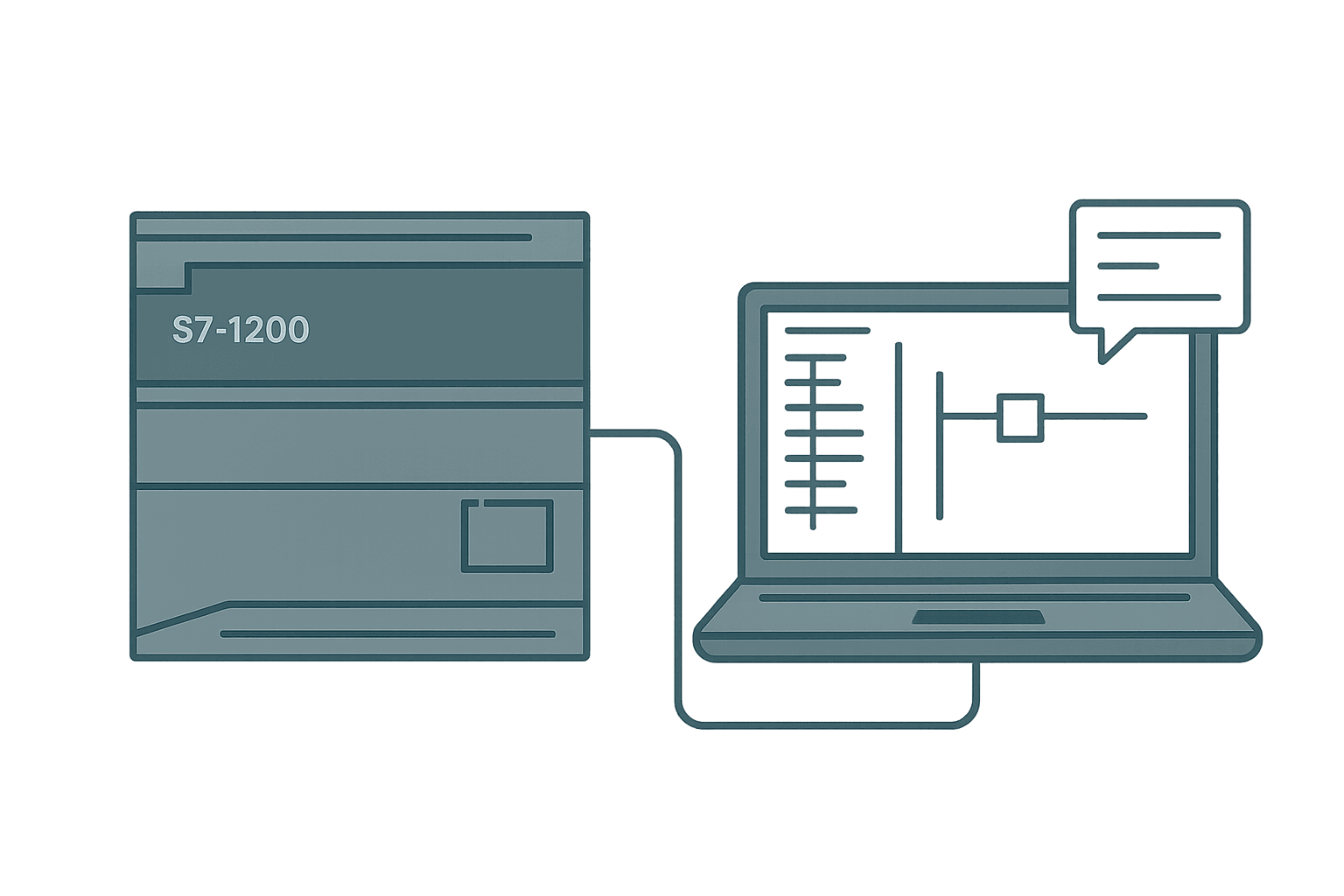
The S7-1200 is probably the most common entry-point PLC on the Siemens side, and TIA Portal is the only tool you use to program it. If you have never opened TIA Portal before, the sheer number of windows and wizards can make a simple blinking-output feel like a week-long project. It is not that complicated, but the sequence matters. Get it wrong and you spend an hour wondering why the download button is greyed out.
This walkthrough covers everything from opening TIA Portal to watching your output toggle on a real CPU. The example uses a CPU 1214C DC/DC/DC (6ES7 214-1AG40-0XB0) and TIA Portal V18, but the steps map cleanly onto any 1200 variant and V16 or V17 as well.
S7-1200 Hardware You Need Before You Start
- S7-1200 CPU (any 1211C, 1212C, 1214C or 1215C will work for this exercise)
- 24 VDC power supply, 2 A minimum
- Standard RJ-45 Ethernet cable (straight-through or crossover, the CPU auto-detects)
- PC with TIA Portal V16 or later installed and licensed (STEP 7 Basic or Professional)
- Optional: a small 24 VDC indicator lamp to see the output physically
Step 1: Create a New TIA Portal Project
Open TIA Portal and click Create new project on the Portal view start page. Give it a meaningful name like S7_1200_First_Program, set a folder path you can find later, and click Create. TIA Portal opens into the Portal view. Click Open the project view at the bottom left to get to the full IDE.
In the project tree on the left you will see the empty project. Right-click Add new device, select Controller, expand the SIMATIC S7-1200 folder, and navigate to your CPU model. For the 1214C DC/DC/DC that is under CPU 1214C DC/DC/DC > 6ES7 214-1AG40-0XB0 > V4.5. Pick the firmware version that matches what is on your physical CPU (check the label on the front). Click OK.
Step 2: Configure the Hardware in Device View
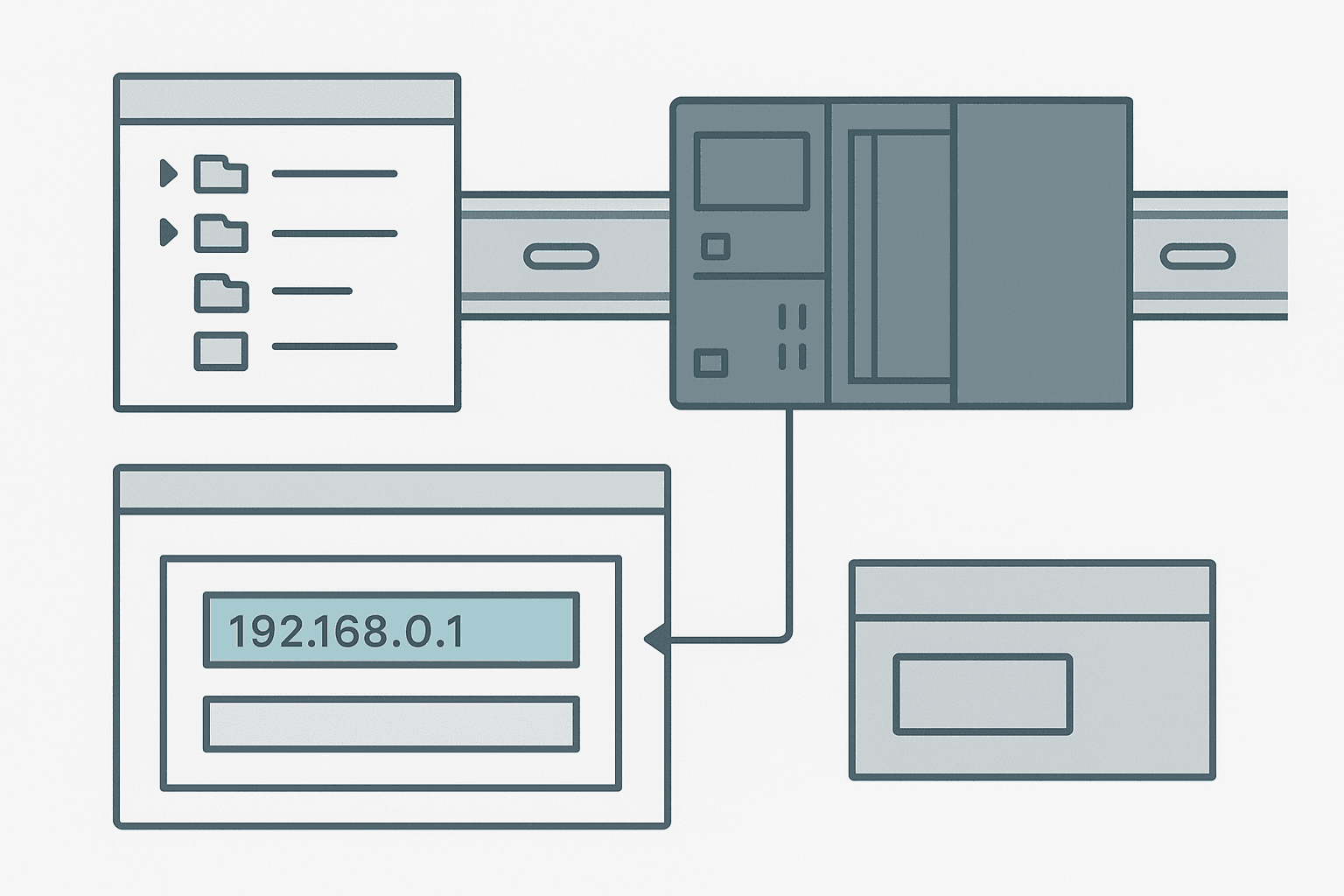
After adding the CPU, TIA Portal drops you into the Device view. This is the hardware configurator. You will see the CPU module on a DIN rail graphic. Click on the CPU image to select it, then look at the Properties panel at the bottom.
Go to Properties > PROFINET interface > Ethernet addresses. Set a static IP address that matches your PC subnet. A typical lab setup is 192.168.0.1 for the CPU and 192.168.0.10 for the PC. Subnet mask 255.255.255.0. Leave the default router blank unless you are going through a managed switch to a different subnet.
That is all the hardware configuration you need for a basic first program. If you had signal boards, SM modules or a CP card you would add those in the Device view catalog on the right, but for a bare CPU you are done. Click Save (Ctrl+S) to commit the configuration.
Step 3: Build the PLC Tag Table
Siemens calls symbolic names for I/O addresses PLC tags. You can write logic directly with absolute addresses like %I0.0 and %Q0.0, but you will hate yourself by rung 20. Tag tables are worth the two minutes they take.
In the project tree, expand your PLC folder and double-click PLC tags > Default tag table. Add three rows:
| Name | Data type | Address | Comment |
|---|---|---|---|
| Start_PB | Bool | %I0.0 | Momentary start pushbutton |
| Stop_PB | Bool | %I0.1 | Normally-closed stop pushbutton input |
| Lamp_Out | Bool | %Q0.0 | Indicator lamp output |
The CPU 1214C has 14 digital inputs starting at %I0.0 and 10 digital outputs starting at %Q0.0. The DC/DC/DC variant means the inputs and outputs are 24 VDC transistor type, not relay. That matters for wiring later but not for the program itself.
Step 4: Write the First Ladder Program in OB1
Every S7-1200 program runs from Organization Block 1 (OB1), which is the main cyclic scan block. In the project tree, double-click Program blocks > Main [OB1]. TIA Portal opens the ladder editor.
The program below is a seal-in circuit with a twist: instead of a plain motor run, it uses a timer to pulse the output on and off automatically once started. That makes it visibly more interesting than a plain coil and shows you how to place a TON block in TIA Portal, which has its own quirks.
S7-1200 Latched Start with Auto-Pulse Output (TIA Portal / OB1). Ladder logic (4 rungs): Rung 0: examine if Start_PB is on (XIC), then either examine if Pulse_Latch is on (XIC), then examine if Stop_PB is off (XIO), then latch output Pulse_Latch (OTL). Rung 1: examine if Stop_PB is on (XIC), then unlatch output Pulse_Latch (OTU). Rung 2: examine if Pulse_Latch is on (XIC), then examine if Pulse_Timer.Q is off (XIO), then energize output Lamp_Out (OTE). Rung 3: examine if Pulse_Latch is on (XIC), then TON on Pulse_Timer. Rung 1: Start_PB (or existing Pulse_Latch seal-in) latches Pulse_Latch if Stop_PB is not pressed. Rung 2: Stop_PB unlatches. Rung 3: Lamp_Out energises while Pulse_Latch is on and the timer output is not yet done, creating a repeating 500 ms blink when logic loops back. Rung 4: TON Pulse_Timer runs for 500 ms from Pulse_Latch; when done, the XIO on Rung 3 drops Lamp_Out for one scan, the timer resets, and the cycle repeats. In TIA Portal you drag the TON instruction from the instruction palette; the DB is created automatically.
The diagram above evaluates one scan. Run these exact rungs on a real scan cycle to watch the latching and the timers behave.
Run this in the simulatorPulse_Timer_DB. It creates the DB automatically. You do not write the DB yourself. This is different from Studio 5000 where timer data lives inside the tag.Step 5: Compile the Project
Click the Compile button (the little brick-wall icon in the toolbar) or press Ctrl+B. The Info panel at the bottom shows the compile output. You want to see zero errors and ideally zero warnings. Common first-time errors:
- Tag not found: you typed a name in a rung that does not match the tag table. Check spelling, including case.
- Data type mismatch: you dropped a DINT tag onto a Bool contact. Wrong type.
- Instance DB conflict: you used the same DB number for two different function blocks. Let TIA Portal auto-assign numbers.
Step 6: Set the PC Network Adapter and Go Online
This is the step most tutorials skip, and it is where people get stuck. Before downloading, you have to tell TIA Portal which network interface on your PC to use.
Go to Online > Download to device (or click the download icon). A dialog opens. Under PG/PC interface, select the Ethernet adapter you have physically connected to the CPU. If you see multiple adapters, pick the one in the same subnet as your CPU IP. Then click Start search. TIA Portal broadcasts on that interface and should find your S7-1200. Select it in the list and click Load.
A pre-download check runs. It will warn you if the hardware configuration in the project does not match what is online (for example, firmware version mismatch or a missing signal module). If everything matches, click Load in the preview window. TIA Portal downloads the hardware configuration first, then the program blocks.
Step 7: Monitor Online and Test the Logic
Click the Go online button (the orange globe icon). TIA Portal connects and the project tree shows orange badges confirming sync. Open OB1 and click Monitoring on (the glasses icon in the toolbar above the ladder). You will see live green highlights on contacts that are true and the current values of all tags.
Press the physical pushbutton wired to %I0.0. The Start_PB contact goes green, Pulse_Latch latches, and Lamp_Out starts toggling every 500 ms. You can watch the Pulse_Timer.ET (elapsed time) count up in the timer block. Press the stop button and everything drops.
If you are using PLCSIM, open the SIM table from the toolbar, add Start_PB and Stop_PB, and toggle their values with the checkbox. No hardware required.
Common S7-1200 Gotchas in TIA Portal
- The Stop_PB input should be wired as a normally-closed contact in hardware but read as a normally-open tag in software if you want fail-safe behaviour. If you wire NC and use an XIC in logic, pressing the button opens the circuit, the input goes FALSE, and the XIC drops. That is correct E-stop logic. Wiring NO and using an XIO is not fail-safe.
- The 1214C DC/DC/DC outputs are sourcing (PNP). If you wire a sinking load you get nothing. Check your load type before you assume the program is wrong.
- TIA Portal saves frequently but it does not auto-compile. A save icon does not mean the program on the CPU is updated. Always compile and download after changes.
- The CPU keeps its program through a power cycle by default. You do not need a memory card for basic operation, but a SIMATIC Memory Card is required if you want to transfer the program to another CPU without a PC.
- CPU 1211C has only 6 DI and 4 DQ. If your tag table references %I0.6 or higher on that model, you will get a hardware config error.
What to Do After Your First Program Works
Once you have a running program, the next natural steps on the S7-1200 are adding a Function Block (FB) so your logic is reusable, setting up a Global DB for shared data, and wiring an analog input. If you are building an HMI alongside this, the TIA Portal HMI programming guide covers connecting a KTP panel to the same CPU and mapping tags directly from the PLC tag table, which is one of the cleanest workflows in any vendor ecosystem.
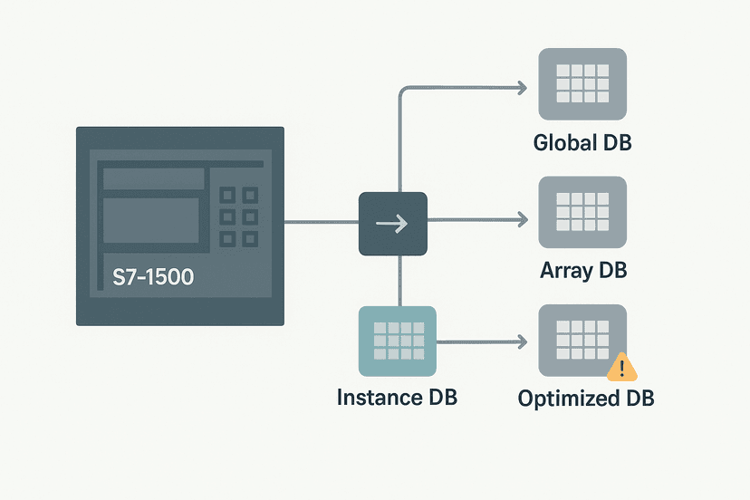
For data blocks specifically, the TIA Portal Data Blocks post explains the difference between Global DBs, Instance DBs and Optimized access, which will become relevant the moment you start writing FBs.
The S7-1200 CPU 1214C has a 125 kHz onboard HSC (High Speed Counter) and two 100 kHz pulse outputs for simple motion, a Web server you can enable for browser-based diagnostics, and built-in PID blocks you can drop into a cyclic interrupt OB. None of that needs extra hardware. For a compact PLC, it punches well above its price point.
Frequently asked questions
Which TIA Portal version works with the S7-1200?
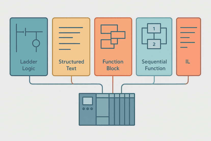
Can I program the S7-1200 in Structured Text instead of ladder?
What is the default IP address of a new S7-1200 CPU?
Do I need a SIMATIC Memory Card to run the S7-1200?
Why is my S7-1200 output not turning on even though the rung is true?
What is the scan cycle time of the S7-1200?
Now build it
You have just read about XIC and XIO. Reading a rung and making one behave are different skills, and the second one is the job.
Start / Stop Circuit
Beginnerabout 10 minThe first circuit every controls engineer learns: a motor that starts on a button press, keeps running when the button is released, and stops on a stop button, with stop always winning.
Build this rungFree, no signup, runs in your browser. See all 16 exercises.
Was this helpful?