PLC I/O Fault Diagnosis with a Multimeter
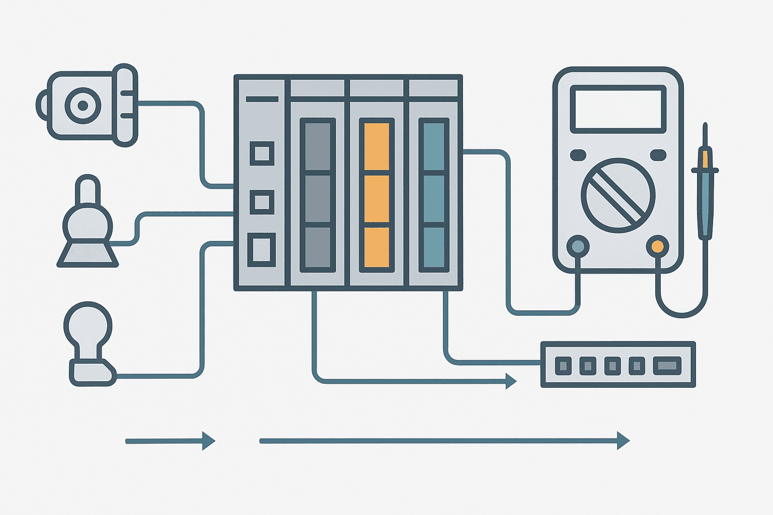
A PLC input card that refuses to pick up, or an output that drives itself to 24 V but the field device never moves: both situations feel like a mystery until you apply a systematic multimeter test sequence. Random probe-poking wastes time. A repeatable process gets you to the fault in minutes, not hours.
This guide covers discrete DC inputs and outputs because those are what you'll be staring at 80% of the time on a modern 24 VDC control system. The same logic applies to 120 VAC I/O but with the obvious safety precautions around mains voltage.
What You Need Before You Start
- A CAT III rated multimeter (Fluke 117 or equivalent). CAT III minimum on any panel connected to mains.
- The I/O wiring diagram for the specific machine, not a generic P&ID.
- PLC online monitoring access so you can see the actual bit status alongside your physical measurements.
- A known-good 24 VDC reference point at the power supply or distribution terminal.
- The module datasheet: you need to know the input threshold voltage and the output current rating.
PLC Input Fault Diagnosis: The Three-Point Test
When a PLC input bit stays OFF but you believe the sensor should be triggering it, there are exactly three places the fault can live: the field device itself, the wiring between device and terminal, or the input card. You test them in that order because the field device and wiring are far more likely to fail than the card.
Step 1: Measure Voltage at the Input Terminal
Set your meter to DC volts. Place the red probe on the input terminal screw (the wire coming from the field device) and the black probe on the 0 V common of the same I/O group. Activate the sensor or switch manually if you can do so safely.
- You read 18 to 30 V and the PLC bit is ON: input card and wiring are fine, look elsewhere.
- You read 18 to 30 V and the PLC bit stays OFF: the input card is suspect, or the input threshold is set incorrectly on a configurable module.
- You read 0 V: the signal is not reaching the terminal. Go to step 2.
- You read 5 to 15 V: leakage from a solid-state sensor or a wiring fault. The input may be floating above the OFF threshold but below the ON threshold.
Step 2: Measure Voltage at the Sensor Output
Move the red probe to the sensor output wire at the junction box or cable gland, still using the same 0 V reference. If you now see the correct 24 V, the fault is in the cable run between the junction box and the panel terminal. Check for chafed insulation, a pulled terminal, or a corroded ferrule.
If you still read 0 V at the sensor output when it should be switching, power-check the sensor supply. Measure between the sensor positive supply pin and 0 V. No supply voltage means a blown fuse on the sensor circuit or an open in the supply wiring. Supply present but output still 0 V: the sensor itself has failed.
Step 3: Verify the Input Card Itself
If your meter shows the correct voltage at the terminal but the bit is stubbornly OFF in the PLC, try this: disconnect the field wiring and apply 24 V directly to the input terminal from a known-good supply with a short jumper wire. If the bit still does not go ON, the card channel is dead. If it does go ON, there's something wrong with your reference common or the wiring introduced a small resistance that's dropping voltage under the card's load.
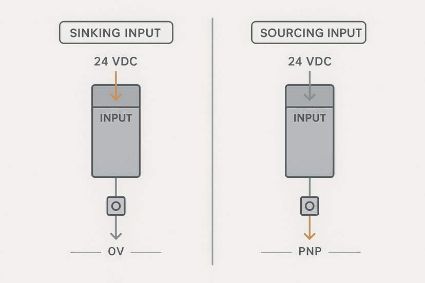
One gotcha: on sinking input cards, the common is shared. A broken common wire takes out an entire group of inputs at once. If multiple adjacent inputs all fail together, check the common terminal first. See Sinking vs Sourcing PLC I/O: Wiring It Right for a full breakdown of how the current path works in each configuration.
PLC Output Fault Diagnosis: Load Testing and Coil Checks
Output faults are slightly different because the PLC is now the source of the signal. The PLC bit might be ON in the software but the field device still does not move. Or the output turns on but trips instantly because of an overcurrent.
Step 1: Confirm the PLC Bit is Actually ON
Go online to the PLC and force the output bit ON if the process allows it. Watch the status LED on the output card. If the LED lights up, the card is driving the channel. If it does not light, check whether the output is protected by a group fuse or electronic protection on the module itself. Some Rockwell 1769-OB16 cards have a blown-fuse indicator bit in the module status word, worth reading before pulling the panel apart.
Step 2: Measure Output Voltage Under Load
With the bit forced ON, measure DC voltage between the output terminal and the 0 V common. A healthy transistor output will be within 1 V of the supply voltage (23 to 24 V on a 24 VDC system). If you read full supply voltage but the device does not run, the fault is in the load circuit: broken wire, open coil, or a missing return path.
If you read 0 V at the terminal with the bit ON, the transistor driver is dead or the module's internal protection has tripped. Some modules, like the Beckhoff EL2008 or Phoenix Contact Axioline, have electronic overcurrent protection that latches off and needs a power cycle or a specific reset bit to recover.
Step 3: Test the Load Device Separately
Disconnect the load from the output terminal. Measure the coil resistance of a relay or solenoid with the meter on the resistance setting. A 24 VDC solenoid coil typically reads 20 to 100 ohms depending on power rating. Open circuit (OL on your meter) means a burnt coil. A reading close to zero means a shorted coil that may have already killed the output transistor.
With the load disconnected and the bit forced ON, measure the output terminal voltage again. If it now shows correct voltage, the load was pulling it down: check the coil resistance and compare to the output card's current limit. A 0.5 A rated output card driving a 0.8 A coil will thermal-trip every time.
| Symptom | Meter Reading | Most Likely Cause |
|---|---|---|
| Input bit stays OFF, sensor triggered | 24 V at input terminal | Dead input channel or card fault |
| Input bit stays OFF, sensor triggered | 0 V at input terminal | Open wiring or sensor output fault |
| Input bit stays OFF, sensor triggered | 8 to 14 V at input terminal | Sensor leakage or wrong common reference |
| Multiple inputs dead | 0 V on common terminal | Broken common wire or blown group fuse |
| Output bit ON, device does not run | 24 V at output terminal, 0 V at device | Open field wiring or broken return path |
| Output bit ON, device does not run | 0 V at output terminal | Dead transistor or latched overcurrent protection |
| Output trips immediately on enable | Voltage collapses to 0 V | Shorted coil or load exceeds card current rating |
| Output LED on, no voltage at terminal | 0 V at terminal | Blown fuse on output group |
Continuity Testing: When and How
Continuity checks are useful for wiring verification but only with the circuit de-energised. Trying to run a continuity test on a live 24 VDC circuit will give you a beep regardless of the fault because the meter's test current is swamped by the supply.
The best time to use continuity is when you have an open-circuit fault and you need to find where in a 20-metre cable run the break is. Disconnect both ends of the suspect wire. Beep from one end to the other. If you get continuity, the wire is intact and the fault is at a termination point: a loose ferrule, a failed push-in spring terminal, or a stripped screw. These account for a surprisingly large proportion of intermittent input faults on older panels.
PLC Online Monitoring Alongside the Meter
The multimeter and the PLC software together are far more powerful than either alone. While your meter measures the physical voltage, the PLC's online monitor shows you the logical state of every bit in real time. A mismatch between the two is the fastest path to the fault.
For example: your meter reads 22 V at the input terminal, the LED on the card is lit, but the bit in the processor is OFF. That tells you the card is receiving the signal but the software is not seeing it. Possible causes include a forced-off condition in the program, an incorrect I/O tree mapping after a module replacement, or a faulted slot that has been inhibited. Check the I/O tree in your programming software before replacing any hardware. For Rockwell platforms, the PLC Troubleshooting with Online Monitoring post goes into that process in detail.
Five Mistakes That Cost You an Hour
- Measuring voltage with the wrong 0 V reference. Always verify which common terminal belongs to the I/O group you're testing.
- Using continuity mode on a live circuit and getting a false 'good' result from the supply voltage.
- Blaming the input card before testing the sensor supply voltage. A dead 24 V supply kills every sensor on that circuit.
- Forgetting that some output modules have electronic protection that latches off and needs a deliberate reset, not a card swap.
- Replacing a dead output transistor without checking the load coil resistance first. A shorted coil will kill the replacement card just as fast.
A Worked Example: Conveyor Jam Sensor Input Refuses to Clear
Here's a real-world scenario. A jam sensor on a conveyor reads as faulted even after the jam is cleared and the sensor LED is off. The bit stays ON in the PLC.
- Measure voltage at the input terminal with sensor LED off: reading is 4 V. Should be 0 V for a logic OFF.
- Check the sensor datasheet: it's a solid-state PNP output with a rated leakage current of 0.5 mA at 24 V supply.
- Calculate the leakage voltage: 0.5 mA through the 10 kΩ input impedance of the card = 5 V. Enough to keep a borderline input energised.
- Solution: add a 2.2 kΩ bleed resistor across the input terminal to 0 V. This drops the leakage voltage to under 1 V, well below the OFF threshold.
- Alternatively, specify a sensor with lower leakage or switch to a card with lower input impedance.
This is one of those faults that looks like a wiring problem, then looks like a sensor problem, and eventually gets blamed on 'interference' until someone actually does the math. Four volts of leakage from a perfectly healthy PNP sensor is not a defect: it's physics. Know your card's input impedance and your sensor's residual current spec.
Frequently asked questions
How do I test a PLC input with a multimeter?
Why is my PLC output ON in software but the device does not run?
Can I use the continuity setting on a live PLC I/O circuit?
What causes a PLC input to read partial voltage (e.g. 8-14 V) instead of 0 or 24 V?
Why do multiple PLC inputs fail at the same time?
How do I know if a PLC output transistor is dead?
Learn this by building it
There is a PLC in this site. It runs a real scan engine, checks your logic against the same tests a working machine would fail, and needs no download and no account.
Open the exercisesFree, no signup, runs in your browser. See all 16 exercises.
Was this helpful?