Ladder Logic Interview Questions: Real Answers
Ladder logic interviews catch a lot of candidates off guard. The questions look simple on the surface: what does XIC do, how does a timer work. But interviewers are really testing whether you understand why things work the way they do, not just the syntax. A candidate who can quote the instruction name but can't explain a duplicate coil conflict or a scan-cycle race condition isn't going to survive day one on a real project.
What Are Ladder Logic Interview Questions?
Ladder logic interview questions test a candidate's understanding of IEC 61131-3 ladder diagram programming: how contacts and coils behave, how the PLC scan cycle processes logic, how timers and counters are used, and how common circuits like seal-ins and latches are built. A strong answer goes beyond definitions and explains real-world implications, like what happens when you misuse an OTE on two rungs, or why a high-speed sensor can't use a standard CTU counter.
Contacts and Coils: The Foundation Questions
These come up in almost every interview and the answers need to be crisp. Fumbling the basics signals inexperience even if you've been working with PLCs for years.
Q1: What is the difference between XIC and XIO?
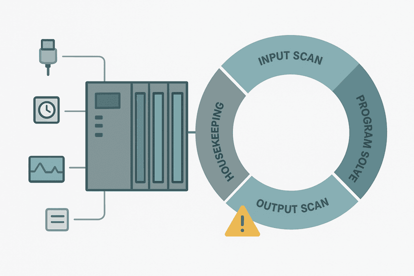
XIC (Examine If Closed) passes power when its tag bit is 1. XIO (Examine If Open) passes power when its tag bit is 0. The critical thing to nail in an interview: both instructions examine the value in the input image table, not the live hardware state. The image table is captured at the start of the scan, so the logic sees a snapshot, not a live wire. This is foundational to understanding the PLC scan cycle and timing faults.
Q2: What is the difference between OTE, OTL and OTU?
OTE (Output Energize) is non-retentive: it follows the rung every scan. OTL (Output Latch) sets a bit and holds it regardless of rung state. OTU (Output Unlatch) clears that same bit. OTL and OTU always come as a pair and they can be on completely different rungs, even in different routines. A good follow-up point: the latch state survives a PLC mode change from Run to Program and back, which OTE does not guarantee.
Q3: What happens with two OTE coils at the same address?
The last rung wins. The PLC writes the output image table as it scans from top to bottom, so rung 50's OTE overwrites rung 10's OTE result for the same bit. Some platforms warn you, but many compile without error. In practice this causes infuriating intermittent behaviour that's hard to trace. The fix is to restructure logic so only one rung controls each coil, or switch to OTL/OTU pairs.
Q4: Draw a seal-in circuit and explain how it works
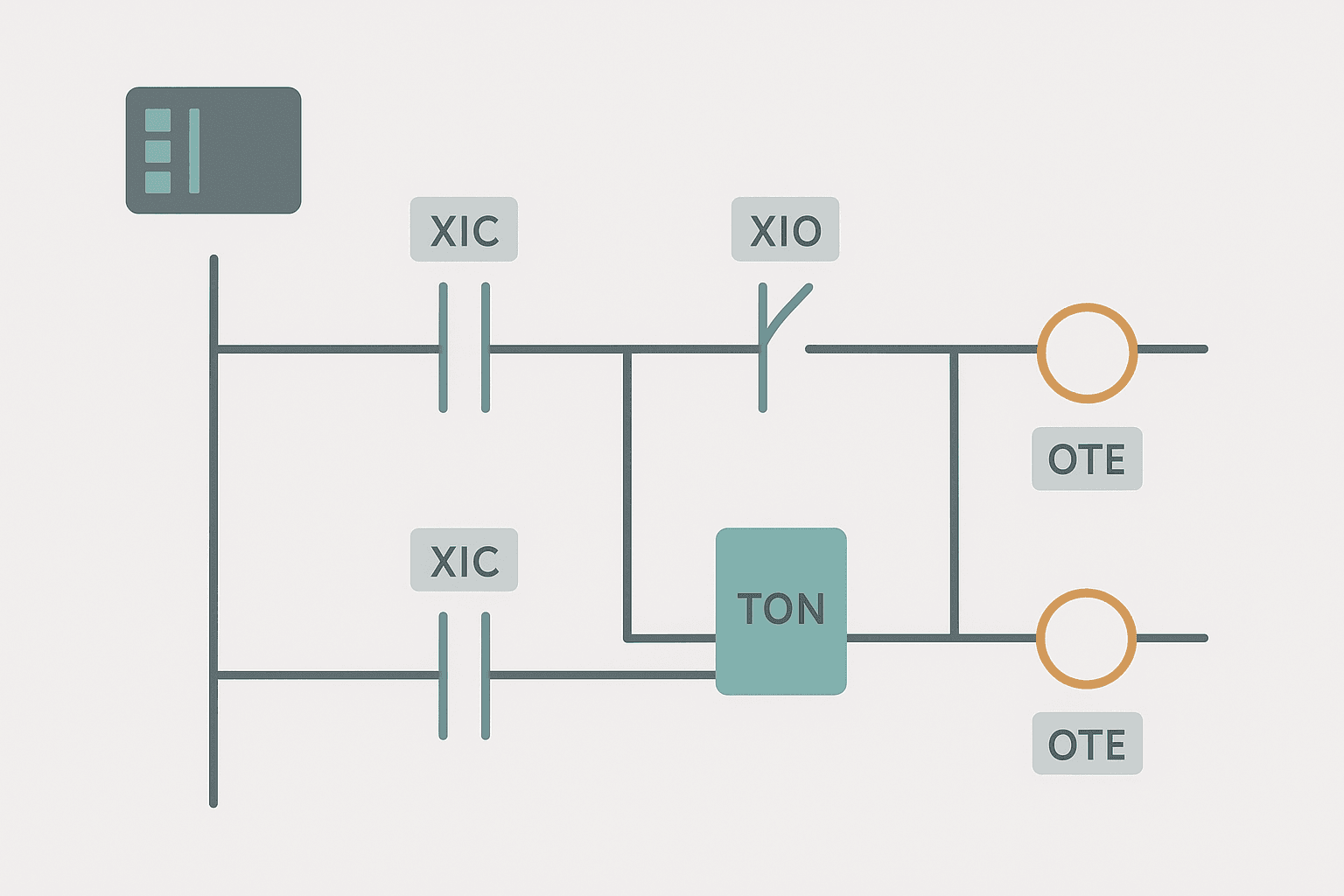
This is a classic. The interviewer wants to see whether you can build it from first principles. A normally open Start contact in series with a normally closed Stop contact drives the output coil. A normally open contact of that same output coil is wired in parallel with the Start contact. Once Start is pressed and the coil energizes, its own contact keeps the rung true after Start releases. Stop breaks the rung. This is the software equivalent of a self-holding relay circuit.
Seal-In Circuit With Fault Interlock (Generic Ladder). Ladder logic (2 rungs): Rung 0: either examine if Start_PB is on (XIC), or examine if Motor_Run is on (XIC), then examine if Stop_PB is off (XIO), then examine if OverTemp_Fault is off (XIO), then energize output Motor_Run (OTE). Rung 1: examine if Motor_Run is on (XIC), then energize output Motor_Output (OTE). Rung 1: Start pushbutton latches via Motor_Run contact in parallel (seal-in). Stop PB and an over-temperature fault both break the rung and drop the coil. Rung 2: the physical output only energizes when the internal Motor_Run bit is true, keeping the output isolated from the interlock logic. This is a common interview pattern: separate control logic from the physical output rung.
The diagram above evaluates one scan. Run these exact rungs on a real scan cycle to watch the latching and the timers behave.
Run this in the simulatorTimer and Counter Questions
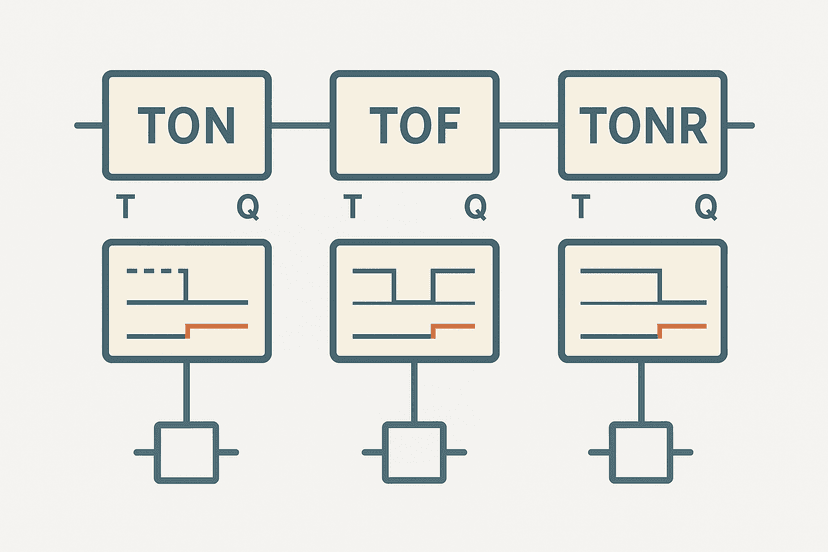
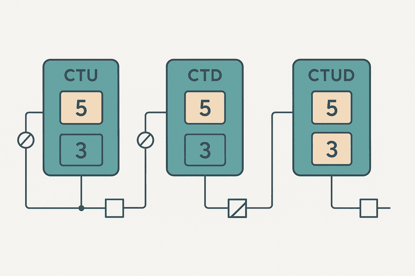
Timers and counters trip up candidates who've only seen them used, not understood them. The TON, TOF and TONR timer differences are a very common interview topic, and CTU, CTD and CTUD counter instructions come up right alongside them.
Q5: What happens to a TON timer if the rung goes false before it finishes?
The accumulator resets to zero. The Enable bit (EN) clears. The Done bit (DN) never sets. If you need the timer to hold its value across a false rung state, you need a retentive timer, TONR in Rockwell or RTO in some other platforms. This distinction matters on any application tracking machine run-hours or accumulated soak time.
Q6: What is TOF and when would you use it instead of TON?
TOF (Timer Off Delay) starts counting when the rung goes false and keeps its output true during the delay. Classic use cases: a fan that keeps running for 30 seconds after a motor stops (purge delay), or a lamp that stays on briefly after a button releases. TON starts on a true rung; TOF starts on a false rung. Candidates often confuse the two or can't describe a real use case, which is what separates a good answer from a great one.
Q7: Can a standard CTU counter keep up with a proximity sensor running at 50 Hz?
Almost certainly not. A 50 Hz signal means a pulse every 20 ms. If the PLC scan time is 10 ms, there's a chance of catching each pulse, but at 20 ms scan time you'll miss every other one. And a CTU only increments on a 0-to-1 transition, so the pulse has to stay high for at least one full scan. For anything above a few pulses per second you need a dedicated High Speed Counter (HSC) input that counts in hardware, independent of the scan cycle.
Q8: How do you reset a CTU counter?
Drive the Reset input (R) of the CTU instruction true, or use a separate RES instruction pointing at the counter tag. When reset, the accumulated value goes to zero and the Done bit clears. A common mistake is using RES without also clearing the DN bit check downstream, which can cause a one-scan logic glitch on the rung that was gating on DN.
Scan Cycle and Execution Order Questions
This is where intermediate candidates separate from beginners. Scan cycle questions reveal whether you've actually debugged timing problems in the field.
Q9: Why might a physical input change not be seen by ladder logic until the next scan?
Because the PLC copies physical inputs into the input image table at the start of the scan, before executing any ladder logic. If a signal changes after that snapshot is taken, the ladder sees the old value until the next scan. On a PLC with a 20 ms scan time, an input that arrives late in the scan is effectively delayed by almost one full cycle. This is why fast events need hardware interrupts or HSC inputs, not polled ladder logic. Understanding this also helps with PLC troubleshooting using online monitoring.
Q10: What is a one-shot instruction and why can't you use a regular XIC for the same purpose?
A one-shot (OSR for rising edge, OSF for falling edge) produces a true output for exactly one scan cycle at the moment a transition is detected. If you use a plain XIC contact on a bit that stays true for multiple scans, the downstream logic (a CTU increment, a latch coil) fires every scan, not once. That's the difference. One-shots are essential for any increment or latch that should respond to an event, not a sustained state.
Q11: What is program scan time and what inflates it?
Scan time is the time to complete one full scan cycle: read inputs, execute all ladder logic, write outputs, service comms. It inflates when you add more rungs, call heavy function blocks, process large arrays, or handle communication tasks inline with the scan. Typical scan times run from 1 ms to 50 ms depending on CPU class and program size. A bloated scan time can cause missed inputs, sluggish response, or watchdog faults. You'd diagnose this with online monitoring tools and check the CPU's scan time diagnostic register.
Practical Circuit and Application Questions
These questions reveal whether you can actually build something, not just recite definitions.
Q12: How do you wire a PNP sensor to a PLC input, and what does that look like in ladder logic?
A PNP (sourcing) sensor drives the input terminal high when it detects a target. The input module needs to be wired for sinking (NPN input type) to accept that signal, or you need a sourcing input module. In ladder logic, the input address appears as an XIC contact that goes true when the sensor fires. The electrical wiring and the ladder symbol are two separate concerns. See the full wiring detail in 3-wire sensor wiring: PNP vs NPN to PLC inputs and sinking vs sourcing PLC I/O.
Q13: How would you implement a 5-second on-delay before a conveyor starts?
Use a TON timer with a 5000 ms preset. The start command energizes the timer rung. Once the timer's DN bit sets, an XIC(Timer.DN) contact drives the conveyor output OTE. If the start command drops before 5 seconds, the timer resets and the conveyor never starts. Simple, but interviewers want to see you describe it in terms of specific instructions, not just say 'use a timer'.
Q14: What is the difference between a physical E-stop and an E-stop in ladder logic?
A physical E-stop in a hardwired circuit cuts power to the hazardous output directly, independent of the PLC. A ladder logic E-stop is just a software XIO contact that drops an output coil. If the PLC CPU faults, the ladder logic E-stop does nothing. That's why functional safety standards like IEC 62061 require hardwired safety circuits for dangerous stopping functions. The IEC 62061 SIL levels guide and emergency stop circuit wiring cover this properly. Never treat a software interlock as a safety function.
Q15: How do you handle an analog input in ladder logic?
The PLC's analog input module converts a 4-20 mA or 0-10 V signal into a raw integer (typically 0-32767 or 0-4095 depending on resolution). That raw count sits in a memory register. A scaling calculation converts it to engineering units. In ladder logic you'd use a CPT (Compute) or MOV instruction to scale it, or in Structured Text a simple formula. The 4-20 mA scaling formula guide and analog input wiring walkthrough are worth reading before any interview that involves process control.
Harder Questions That Separate Good Candidates
Q16: What are the five IEC 61131-3 programming languages and when would you choose ladder over structured text?
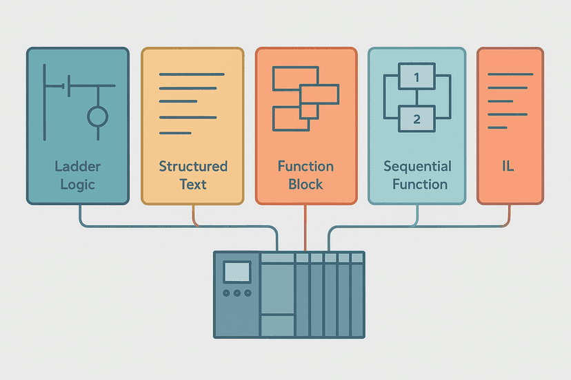
IEC 61131-3 defines Ladder Diagram (LD), Function Block Diagram (FBD), Structured Text (ST), Instruction List (IL, now deprecated) and Sequential Function Chart (SFC). Ladder suits discrete I/O logic, relay-replacement circuits and anything where field technicians need to read and troubleshoot the code without software training. Structured text is better for math-heavy calculations, analog scaling and loops. All five languages are compared here. A mature project often uses both.
Q17: What is indirect addressing and why is it useful?
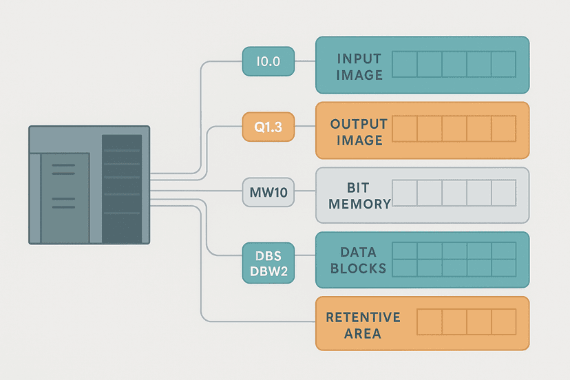
Indirect addressing lets you use a variable as the index into an array rather than a fixed address. For example, Recipe[RecipeIndex].SetPoint uses the value of RecipeIndex to select which recipe element to read. This is powerful for multi-recipe machines, sequential steppers and lookup tables. In Rockwell Logix it's done naturally with array indexing. In older platforms like SLC-500 you'd use pointer registers. Understanding PLC memory and addressing is a prerequisite for answering this well.
Q18: How would you troubleshoot a rung that looks true in online monitoring but the output isn't energizing?
Check these in order: Is the output forced? Is there a duplicate OTE downstream that's overwriting it? Is the physical output wired correctly and is the module powered? Is the output in fault state (blown fuse on the module)? Online monitoring shows the image table, not the physical terminal. The terminal could be dead even if the bit is true. Use a multimeter to confirm voltage at the output terminal. PLC I/O fault diagnosis with a multimeter covers exactly this.
Q19: What is the difference between a PLC and a DCS in terms of how they execute logic?
A PLC executes its scan cyclically and deterministically, completing the full ladder program every scan. A DCS typically organizes control in function blocks executed at configurable intervals, often prioritized by loop or module. PLCs are optimized for fast discrete I/O and sequential logic. DCS systems are designed for continuous process control with tighter integration of alarming, historian and operator displays. For most machine control and packaging applications, a PLC is the right tool. For a refinery or chemical plant, a DCS is more appropriate.
Q20: A customer says their machine randomly stops. How do you start diagnosing it using only what's in the PLC?
Start with the CPU diagnostic buffer or fault log: it records what was happening at the moment of the stop. Check for watchdog faults, I/O module faults, or communication errors. Then look at the logic: which coil dropped, and trace back through its interlock chain. Use trend logging or a data log if the PLC supports it to capture the state of critical bits over time. Online monitoring for PLC troubleshooting is the right starting point. Intermittent faults from sensors are also a common culprit; see intermittent sensor fault troubleshooting.
| Instruction | Type | Behaviour | Common Use |
|---|---|---|---|
| XIC | Contact | True when bit = 1 | Normal interlock, permissive |
| XIO | Contact | True when bit = 0 | Normally closed interlock, fault check |
| OTE | Coil | Follows rung every scan | Standard output, motor run command |
| OTL | Coil | Latches bit on true rung | Fault latch, alarm hold |
| OTU | Coil | Unlatches bit on true rung | Fault clear, alarm reset |
| OSR | Contact | True for one scan on 0-to-1 edge | Counter increment, event trigger |
Five More Questions Worth Preparing
- Q21: What is a watchdog timer in a PLC? It's a hardware timer that resets every scan. If the scan takes too long (CPU overloaded, infinite loop), the watchdog expires and faults the CPU to a safe state. Typical watchdog limits are 150 ms to 500 ms depending on the platform.
- Q22: How do you share data between two PLCs? Common methods: EtherNet/IP produced/consumed tags (Rockwell), PROFINET IO (Siemens), Modbus TCP over Ethernet, or mapped I/O over a fieldbus. The choice depends on vendor, network topology and update rate requirements.
- Q23: What does forcing an I/O point do and when is it dangerous? A force overrides the image table value regardless of the physical input or output state. It's useful for testing, but leaving a force in place in production can mask real faults or prevent a machine from stopping safely. Always document and remove forces after testing.
- Q24: What is program organization in a Rockwell Logix project? Tasks contain programs, which contain routines. A periodic task runs at a fixed interval (e.g., every 10 ms). A continuous task runs as fast as the CPU allows. An event task fires on a trigger. Understanding this helps when explaining why some logic runs faster than others.
- Q25: How do HMI tags map to PLC ladder addresses? The HMI communicates with the PLC via a driver (EtherNet/IP, Modbus, PROFINET) and reads or writes specific memory addresses or tag names. In TIA Portal the HMI tag links to a PLC DB tag. In Studio 5000, the HMI reads controller-scope tags by name. HMI tag linking and PLC address mapping explains the mechanics in detail.
What to Read Next
If these questions exposed gaps, fill them systematically. Work through the TON, TOF and TONR timer deep-dive and the CTU, CTD and CTUD counter guide to get timers and counters solid. Then practice building real circuits: the PLC pump station exercise and traffic light PLC exercise are good hands-on drills that replicate exactly the kind of circuits interviewers ask you to sketch on a whiteboard.
Frequently asked questions
What is the difference between XIC and XIO in ladder logic?
What is the difference between OTE, OTL and OTU coils?
What happens if you put two OTE coils with the same address on different rungs?
What is a seal-in circuit and why is it used?
How does a TON timer work in ladder logic?
What is the PLC scan cycle and why does its order matter?
What causes a one-scan pulse in ladder logic?
Can a CTU counter count faster than the PLC scan rate?
What is the difference between a retentive and non-retentive timer?
How do you stop a motor safely in ladder logic without a physical E-stop in the PLC program?
Now build it
You have just read about OTE and XIC and XIO. Reading a rung and making one behave are different skills, and the second one is the job.
Start / Stop Circuit
Beginnerabout 10 minThe first circuit every controls engineer learns: a motor that starts on a button press, keeps running when the button is released, and stops on a stop button, with stop always winning.
Build this rungFree, no signup, runs in your browser. See all 16 exercises.
Was this helpful?