PLC Pump Station Exercise: Ladder Logic
Pump station control is one of the most common real-world PLC applications you'll encounter. Municipalities, food plants, chemical facilities, HVAC systems: they all have wet wells or sumps with two pumps wired up in a duty/standby arrangement. The logic looks simple on paper, but there are enough edge cases to trip up anyone who hasn't built it before. This exercise walks you through a full two-pump station from scratch using Rockwell Studio 5000 / CompactLogix tags, covering hand-off-auto (HOA) selection, level-based start/stop, duty pump alternation, run-confirm fault detection, and a high-high alarm.
The Process We're Controlling
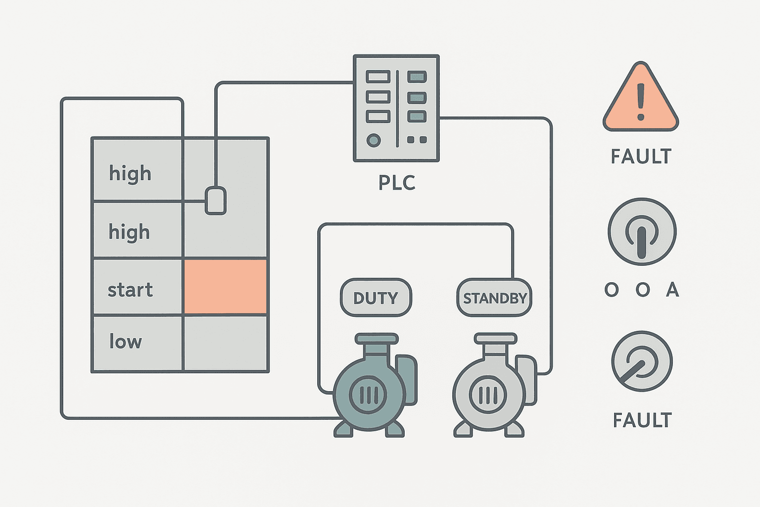
The wet well has four float switches mounted at increasing heights: LS_Low, LS_Start, LS_High, and LS_HighHigh. Floats are normally-open, so they go TRUE when the liquid level rises past them. Two identical submersible pumps (Pump1 and Pump2) can each drain the well. Only one runs at a time under normal conditions. When one pump can't keep up, the standby kicks in.
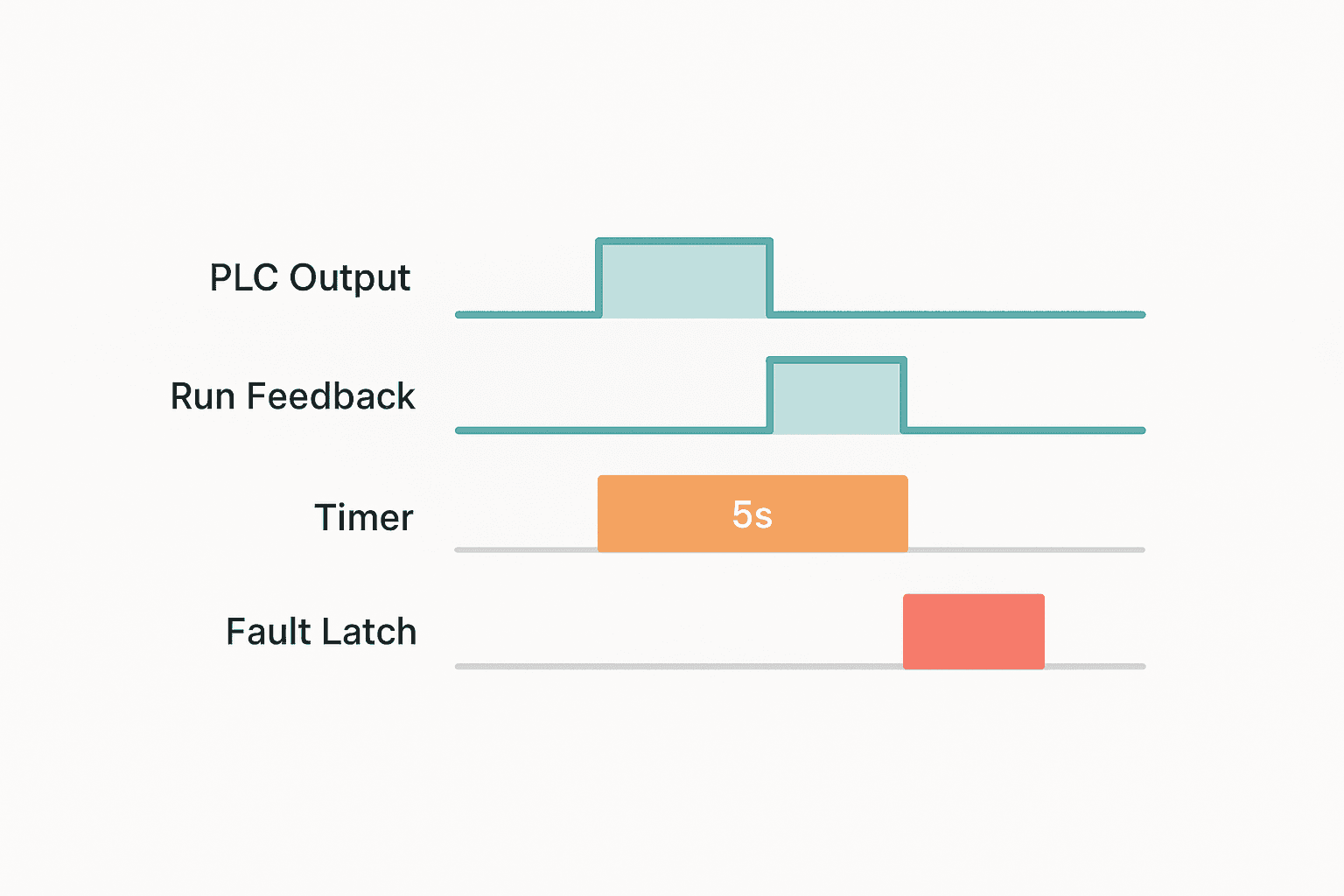
Each pump has a contactor output from the PLC and a run-confirm feedback input wired from an auxiliary contact on that contactor. If the PLC commands a pump on but the run feedback doesn't arrive within 5 seconds, you have a fault: motor tripped, contactor coil failed, cable broken. That failure needs an alarm latch and a handover to the standby pump.
I/O List and Tag Names
| Tag Name | I/O Type | Description |
|---|---|---|
| LS_Low | DI | Float: TRUE when level above low setpoint |
| LS_Start | DI | Float: TRUE when level above start setpoint |
| LS_High | DI | Float: TRUE when level above high setpoint |
| LS_HighHigh | DI | Float: TRUE when level at high-high alarm |
| HOA_P1_Hand | DI | Pump 1 selector: Hand position |
| HOA_P1_Auto | DI | Pump 1 selector: Auto position |
| HOA_P2_Hand | DI | Pump 2 selector: Hand position |
| HOA_P2_Auto | DI | Pump 2 selector: Auto position |
| P1_RunFB | DI | Pump 1 run feedback from contactor aux |
| P2_RunFB | DI | Pump 2 run feedback from contactor aux |
| P1_Output | DO | Pump 1 contactor coil command |
| P2_Output | DO | Pump 2 contactor coil command |
| Alarm_HighHigh | DO | High-high level alarm horn/lamp |
| Alarm_P1_Fault | DO | Pump 1 run-confirm fault indicator |
| Alarm_P2_Fault | DO | Pump 2 run-confirm fault indicator |
| HMI_FaultAck | BOOL (HMI tag) | Operator fault acknowledge momentary |
| Duty_Is_P1 | BOOL (internal) | TRUE = Pump 1 is duty; FALSE = Pump 2 is duty |
| Alternation_Trigger | BOOL (internal) | One-shot to swap duty pump after each cycle |
Logic Structure: Think in Sections
Organise the ladder into four routines or rung groups. This keeps it readable when someone else (or you, six months later) has to troubleshoot at 2 AM.
- HOA mode and fault-inhibit logic: determine whether each pump is in Auto, Hand, or faulted/inhibited
- Duty/standby assignment and alternation: decide which pump leads this cycle
- Auto start/stop sequencing: level-float-based run commands
- Run-confirm fault detection and alarm latching: timeout watchdog for each pump
Section 1: HOA Mode and Fault Inhibit
In Hand mode the pump runs regardless of level. In Auto mode the level logic decides. If a pump has a fault latch set, it's removed from auto sequencing entirely until the fault is acknowledged and the selector is cycled through Off and back to Auto. This is how it works on real sites: an operator physically goes to the panel, resets the fault, then puts the selector back.
A key point: the HOA selector wiring matters. On a three-position HOA switch wired to two DI points, both inputs are FALSE in the Off position. Hand gives you DI1 TRUE, Auto gives you DI2 TRUE. Never assume the selector is in a known position at power-up; always check both bits.
Section 2: Duty/Standby Alternation Logic
The simplest and most reliable alternation scheme: after each complete pump cycle (level drops below LS_Low and the running pump stops), flip a BOOL tag called Duty_Is_P1. If it was TRUE, set it FALSE. Next start event, Pump 2 leads. This gives you roughly equal run hours without needing a timer or a counter watching elapsed minutes.
You'll see some engineers use a TONR run-hour accumulator to drive alternation instead. That's fine for applications where one pump might sit idle for weeks, but for a wet well that cycles dozens of times a day the falling-edge alternation is simpler and equally effective. See the TON, TOF and TONR Timers post if you want to explore the accumulating timer approach.
Section 3: Auto Start/Stop Sequencing
The start and stop logic uses the floats as a simple two-point band controller. The duty pump starts when LS_Start goes TRUE and stops when LS_Low goes FALSE (level has dropped back below the low float). The standby pump joins in only if LS_High is still TRUE after the duty pump has been running for 10 seconds, meaning the level is rising faster than one pump can handle.
Section 4: Run-Confirm Fault Detection
This is the rung that actually saves you in the field. The PLC commands the pump output TRUE. You start a 5-second TON timer. If the run-feedback input hasn't gone TRUE by the time the timer expires, the motor hasn't started: latch a fault, kill the output, and if the other pump is available and healthy, command it to start instead.
The timer preset of 5 seconds comes from typical contactor pickup time (under 100 ms) plus motor acceleration (1 to 3 seconds for a small submersible) plus some margin. Don't set it shorter than 3 seconds or you'll nuisance-trip on momentary voltage dips during motor start.
The Ladder: Duty Start and Run-Confirm Fault
Below is the core of Section 3 and Section 4 combined: duty pump auto-start, standby assist, and the run-confirm watchdog for Pump 1. Pump 2 rungs mirror these exactly with the tags swapped. The HOA and alternation logic is wiring and BOOL manipulation that's easier to follow in prose than in a single ladder excerpt.
Pump Station: Duty Start, Standby Assist, Run-Confirm Fault (Studio 5000). Ladder logic (14 rungs): Rung 0: examine if HOA_P1_Auto is on (XIC), then examine if Duty_Is_P1 is on (XIC), then examine if LS_Start is on (XIC), then examine if Alarm_P1_Fault is off (XIO), then latch output P1_Cmd (OTL). Rung 1: examine if P1_Cmd is on (XIC), then examine if P1_RunFB is off (XIO), then TON on P1_StartTimeout. Rung 2: examine if P1_StartTimeout.DN is on (XIC), then examine if P1_FaultTrig is on (XIC), then latch output Alarm_P1_Fault (OTL). Rung 3: examine if P1_FaultTrig is on (XIC), then unlatch output P1_Cmd (OTU). Rung 4: examine if Alarm_P1_Fault is on (XIC), then examine if HMI_FaultAck is on (XIC), then examine if P1_Cmd is off (XIO), then unlatch output Alarm_P1_Fault (OTU). Rung 5: examine if P1_Cmd is on (XIC), then examine if P1_RunFB is on (XIC), then energize output P1_Output (OTE). Rung 6: examine if HOA_P1_Auto is on (XIC), then examine if Duty_Is_P1 is on (XIC), then examine if LS_High is on (XIC), then examine if P1_RunFB is on (XIC), then TON on Standby_Assist_Delay. Rung 7: examine if Standby_Assist_Delay.DN is on (XIC), then examine if Alarm_P2_Fault is off (XIO), then latch output P2_Cmd (OTL). Rung 8: examine if P1_Cmd is on (XIC), then examine if LS_Low is off (XIO), then unlatch output P1_Cmd (OTU). Rung 9: examine if P2_Cmd is on (XIC), then examine if LS_Low is off (XIO), then TON on P2_MinRun. Rung 10: examine if P2_MinRun.DN is on (XIC), then examine if LS_High is off (XIO), then unlatch output P2_Cmd (OTU). Rung 11: examine if HOA_P1_Hand is on (XIC), then energize output P1_Output (OTE). Rung 12: examine if HOA_P2_Hand is on (XIC), then energize output P2_Output (OTE). Rung 13: examine if LS_HighHigh is on (XIC), then energize output Alarm_HighHigh (OTE). Rung 1: Duty Pump 1 auto-start. HOA in Auto, Pump 1 is duty, LS_Start TRUE, no fault: latch P1 run command. Rung 2: Start-confirm watchdog timer. P1 commanded but no run feedback: 5-second TON starts. Rung 3: Timer done triggers one-shot, latches Pump 1 fault alarm. Rung 4: One-shot also unlatches P1 command (kills output). Rung 5: Operator ack clears fault latch when pump is off. Rung 6: Physical output gated by command AND run feedback present (confirms contactor sealed). Rung 7-8: Standby assist. If level still high and duty pump is confirmed running after 10 s, latch standby Pump 2 command (if not faulted). Rungs 9-10: Stop logic. Duty pump stops when level drops below LS_Low. Standby stops only after 15-second minimum run timer clears and LS_High is gone. Rungs 11-12: Hand mode bypass. Pump outputs energised directly regardless of level. Rung 13: High-high alarm coil.
Duty Alternation: The Falling-Edge Flip
Add a rung that watches for the falling edge of P1_Cmd when the level has genuinely dropped (LS_Low FALSE). Use an OSF (one-shot falling) instruction on P1_Cmd. When that one-shot fires, toggle Duty_Is_P1 with a XOR or a simple NOT-copy CPT instruction: Duty_Is_P1 := NOT Duty_Is_P1;. Do the same on P2_Cmd's falling edge so the alternation fires whichever pump was running. Only one of them will be the duty pump, so only one falling edge will occur per drain cycle.
Common Mistakes to Avoid
- Forgetting to check the fault latch in the auto-start rung: without XIO(Alarm_P1_Fault), a faulted pump will repeatedly try to start and immediately fault again every scan.
- Wiring the run-feedback as normally-closed: if the cable breaks or the terminal works loose, a broken-wire condition looks like the pump is running. Wire feedback as normally-open from the contactor aux.
- Not latching the auto-start command: if you use an OTE instead of OTL for the duty pump command, the pump stops the moment LS_Start drops FALSE even if the level hasn't reached LS_Low yet. Use OTL/OTU pairs to hold the command until the stop condition is met.
- Allowing both pumps to start simultaneously in auto: add an XIO(P1_Cmd) condition in the standby assist rung's start path to prevent any race condition at power-up.
- Ignoring the HOA Off position: if both HOA_P1_Hand and HOA_P1_Auto are FALSE, the pump is Off. Make sure auto logic cannot command the output in this state. The HOA_P1_Auto contact at the start of the auto rungs handles this naturally.
Extension Challenges
Once the base logic runs cleanly, extend it. Each of these adds a skill that shows up constantly in real projects.
- Add a TONR accumulating run-hour counter for each pump and trigger a maintenance-due alarm at 2,000 hours. The PLC Counter Instructions post covers CTU behaviour if you want to count run minutes with a periodic trigger instead.
- Replace the float switches with a single 4-20 mA submersible level transmitter and use analog setpoints for start, stop, high and high-high. This forces you to add scaling and deadband logic.
- Add a weekly alternation override: if the same pump has been duty for more than 7 days without a natural alternation cycle (the well never drained completely), force a swap.
- Build a simple HMI faceplate showing current duty pump, run status, fault status, and accumulated run hours for each pump.
Testing Without a Wet Well
You don't need physical hardware to validate this logic. In Studio 5000 online mode, force the float switch tags manually in sequence: force LS_Start TRUE, watch P1 command latch, force P1_RunFB TRUE within 5 seconds, confirm the start timeout timer resets. Then force LS_Low FALSE and confirm P1 stops. Force LS_Start TRUE again for the next cycle: confirm Duty_Is_P1 flipped and P2 now leads.
For fault testing: force P1 command TRUE manually and do NOT force P1_RunFB. Watch the 5-second timer run to DN, the fault latch set, and the output unlatch. Then force LS_Start TRUE again: confirm the standby (P2) starts instead because P1 is faulted. This sequence proves the safety net works before you ever wire up a real motor.
Was this helpful?