Car Wash PLC Exercise: Full Ladder Logic
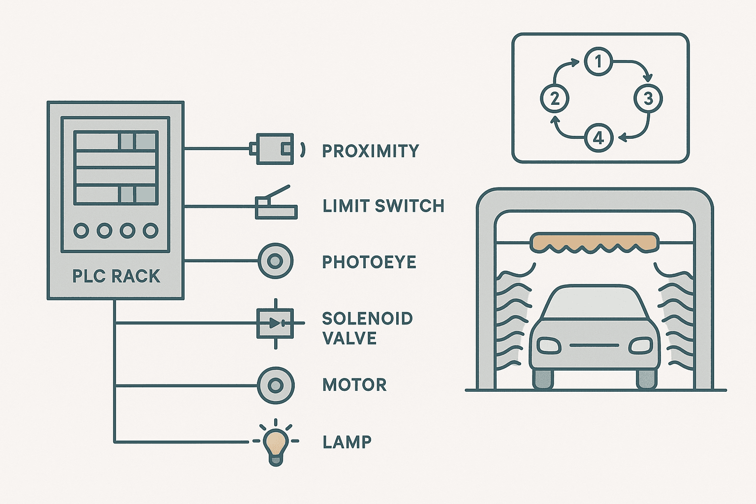
A car wash is one of the best teaching machines in automation. It has a clear start condition, a fixed sequence of timed steps, physical interlocks (is the car in position? is the bay door closed?), and a clean end state. It forces you to think about state management, TON timers chained together, and what happens if a sensor fails mid-cycle. Better than any toy exercise.
This post builds a complete, runnable car wash sequencer in Studio 5000 Ladder Logic. You'll get the full I/O list, the state machine logic, the timer rungs, and the interlocks. If you want to adapt it for CODESYS or GX Works 3, the structure maps directly, only the tag syntax changes.
Car Wash System Description
This is a single-bay automatic car wash. The sequence is: detect vehicle, close entry gate, pre-soak spray, scrub brush pass forward, rinse spray, blower pass, open exit gate. The vehicle does not move. The wash gantry travels back and forth on rails. Keeping the vehicle stationary is a deliberate design choice that makes the limit switch logic simple to reason about.
I/O List
| Tag Name | Type | Description |
|---|---|---|
| VehicleDetect | DI | Photoeye, TRUE when vehicle in bay |
| GantryAtHome | DI | Limit switch, gantry at start (entry) end |
| GantryAtEnd | DI | Limit switch, gantry at exit end |
| StartBtn | DI | Operator pushbutton, momentary |
| EStop | DI | NC E-stop contact, FALSE = emergency |
| EntryGate_Closed | DI | Reed switch, gate fully closed |
| ExitGate_Closed | DI | Reed switch, gate fully closed |
| EntryGate_Sol | DO | Open/close entry gate solenoid |
| ExitGate_Sol | DO | Open/close exit gate solenoid |
| GantryFwd | DO | Drive gantry toward exit end |
| GantryRev | DO | Drive gantry toward home end |
| PreSoak_Sol | DO | Pre-soak spray valve |
| Rinse_Sol | DO | Rinse spray valve |
| Brush_Motor | DO | Scrub brush motor contactor |
| Blower_Motor | DO | Air blower motor contactor |
| CycleActive_Lamp | DO | Amber in-progress lamp |
State Machine: The Right Way to Sequence This
You could code this as a pile of interlocked rungs, but you'll regret it by state 3. Use an integer tag called WashState and one rung per state transition. Each state has a number, a set of outputs it activates, and a condition that advances to the next state. This pattern is sometimes called a sequential function chart in code, and it scales.
| State | Name | Active Outputs | Advance Condition |
|---|---|---|---|
| 0 | Idle | None | VehicleDetect AND StartBtn AND EStop |
| 1 | Gate Close | EntryGate_Sol | EntryGate_Closed AND GantryAtHome |
| 2 | Pre-Soak | PreSoak_Sol, GantryFwd | Soak_Timer.DN (8 s) |
| 3 | Scrub Forward | Brush_Motor, GantryFwd | GantryAtEnd |
| 4 | Rinse Forward | Rinse_Sol, GantryFwd | Rinse_Fwd_Timer.DN (10 s) AND GantryAtEnd |
| 5 | Blower Forward | Blower_Motor, GantryFwd | GantryAtEnd |
| 6 | Gantry Return | GantryRev | GantryAtHome |
| 7 | Exit Gate Open | ExitGate_Sol | Exit_Timer.DN (4 s) |
| 8 | Complete | CycleActive_Lamp off | XIO(VehicleDetect) -> State 0 |
WashState defaults to 0 and nothing moves. That one habit prevents a lot of embarrassing surprises at commissioning.State Transition Rungs
The pattern for each transition rung is: EQU(WashState, N) AND [advance condition] then MOV(N+1, WashState). Below is the structured text equivalent, which is actually more readable for a sequencer this size. After the ST block, you'll find the ladder rung for the scrub step because that's the one with the motor interlock people always get wrong.
// Car Wash Sequencer - Studio 5000 Structured Text (Add-On Instruction or routine)
// All timers pre-declared: Soak_Timer, Rinse_Fwd_Timer, Exit_Timer (TIMER data type)

CASE WashState OF

    0: // Idle
        IF VehicleDetect AND StartBtn AND EStop THEN
            WashState := 1;
        END_IF;

    1: // Close entry gate
        EntryGate_Sol := TRUE;
        IF EntryGate_Closed AND GantryAtHome THEN
            WashState := 2;
        END_IF;

    2: // Pre-soak (timed, gantry creeps forward at low speed)
        PreSoak_Sol := TRUE;
        GantryFwd   := TRUE;
        // TON Soak_Timer, preset 8000 ms
        IF Soak_Timer.DN THEN
            WashState := 3;
        END_IF;

    3: // Scrub brush forward pass
        Brush_Motor := TRUE;
        GantryFwd   := TRUE;
        IF GantryAtEnd THEN
            WashState := 4;
        END_IF;

    4: // Rinse forward (hold at end for 10 s)
        Rinse_Sol := TRUE;
        IF Rinse_Fwd_Timer.DN THEN
            WashState := 5;
        END_IF;

    5: // Blower forward pass
        Blower_Motor := TRUE;
        GantryFwd    := TRUE;
        IF GantryAtEnd THEN
            WashState := 6;
        END_IF;

    6: // Return gantry to home
        GantryRev := TRUE;
        IF GantryAtHome THEN
            WashState := 7;
        END_IF;

    7: // Open exit gate
        ExitGate_Sol := TRUE;
        // TON Exit_Timer, preset 4000 ms
        IF Exit_Timer.DN THEN
            WashState := 8;
        END_IF;

    8: // Wait for vehicle to leave
        IF NOT VehicleDetect THEN
            ExitGate_Sol := FALSE;
            WashState    := 0;
        END_IF;

END_CASE;

// CycleActive lamp: on whenever not idle
CycleActive_Lamp := (WashState > 0) AND (WashState < 8);

// E-stop: force state 0 and kill all motion outputs
IF NOT EStop THEN
    WashState    := 0;
    GantryFwd    := FALSE;
    GantryRev    := FALSE;
    Brush_Motor  := FALSE;
    Blower_Motor := FALSE;
    PreSoak_Sol  := FALSE;
    Rinse_Sol    := FALSE;
END_IF;
Ladder Logic: Scrub Step with Motor Interlock
Here's the ladder rung for State 3 in pure Ladder Diagram. This is the one that trips people up because you need to confirm the gate is actually closed before you energise the brush motor. Notice the EQU contact compares WashState to the constant 3. In Studio 5000 that's an EQU instruction on the rung, treated here as a named contact for readability.
Car Wash: Scrub Step Activation with Gate Interlock (Studio 5000). Ladder logic (5 rungs): Rung 0: examine if State3_Active is on (XIC), then examine if EntryGate_Closed is on (XIC), then examine if ExitGate_Closed is on (XIC), then examine if Brush_FaultLatch is off (XIO), then energize output Brush_Motor (OTE). Rung 1: examine if State3_Active is on (XIC), then examine if EntryGate_Closed is on (XIC), then examine if ExitGate_Closed is on (XIC), then examine if Brush_FaultLatch is off (XIO), then energize output GantryFwd (OTE). Rung 2: examine if Brush_Motor is on (XIC), then examine if Brush_FaultLatch is off (XIO), then TON on Brush_StartTimeout. Rung 3: examine if Brush_StartTimeout.DN is on (XIC), then examine if Brush_Running_FB is off (XIO), then examine if Brush_Fault_OS is on (XIC), then latch output Brush_FaultLatch (OTL). Rung 4: examine if Brush_FaultLatch is on (XIC), then examine if HMI_FaultAck is on (XIC), then examine if Brush_Motor is off (XIO), then unlatch output Brush_FaultLatch (OTU). State3_Active is a BOOL derived from EQU(WashState,3). Both gates must confirm closed before the brush motor energises. A 5-second TON watches for a motor run feedback signal (Brush_Running_FB from a current relay or auxiliary contact). If feedback never arrives, the fault latches and the operator must acknowledge before the cycle can restart. GantryFwd is only allowed when the brush is actually running, preventing a dry gantry travel.
Timer Wiring for the Timed States
States 2, 4 and 7 are timer-gated. Each needs a TON instruction that resets when the state is not active, otherwise the timer carries its accumulated value into the next cycle and the first pre-soak lasts zero seconds. The cleanest way: gate the TON enable contact with the state BOOL, so when WashState moves away from 2, the TON input goes FALSE and the accumulator resets automatically.
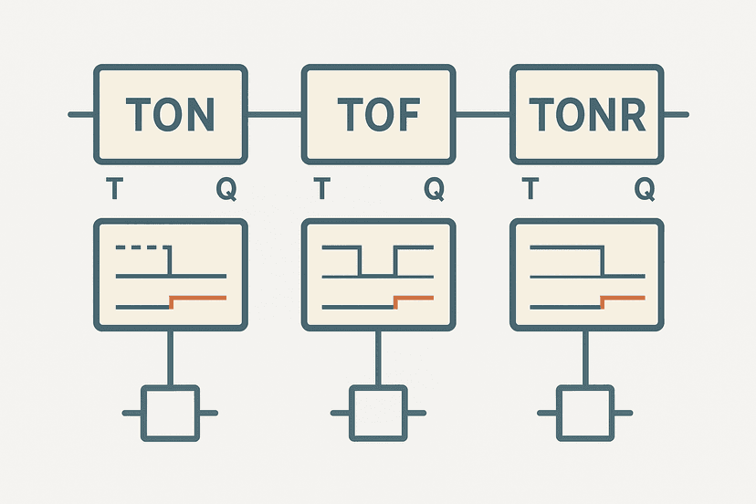
XIC(AlwaysOnBit)TON(Soak_Timer,8000,0) and forget to gate it with the state condition, Soak_Timer keeps accumulating in every state. By the time you reach State 2, it's already done. Gate every timer with its state BOOL, and that problem disappears.In ladder, add a rung like this for State 2:
// Rung: Pre-soak timer (active only in State 2)
// State2_Active = EQU(WashState, 2)
XIC(State2_Active) TON(Soak_Timer, 8000, 0)

// Transition rung: advance to State 3 when timer done
XIC(State2_Active) XIC(Soak_Timer.DN) MOV(3, WashState)
Gantry Direction Interlock: The One You Cannot Skip
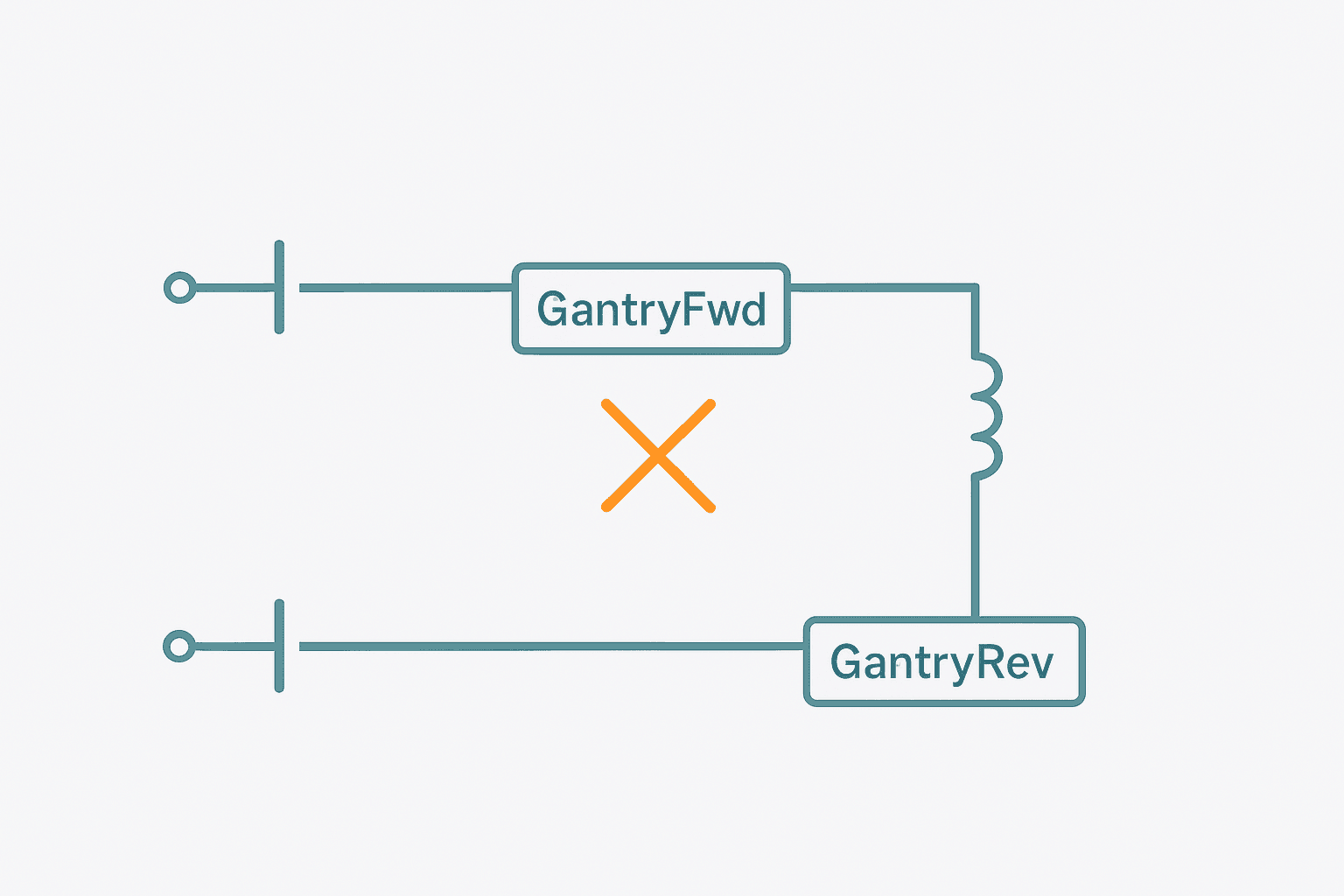
GantryFwd and GantryRev must never be TRUE at the same time or you'll smoke a drive and possibly damage the gantry mechanics. Add a hardware interlock at the drive level if the drive supports it, and add a software interlock in the PLC as a second layer. The software rung is just XIO(GantryRev) in series with GantryFwd, and XIO(GantryFwd) in series with GantryRev. Cheap insurance.
Exercises to Take This Further
Once the basic sequence runs, try these to build real competence:
- Add a wash cycle counter (CTU) that increments each time State 8 completes, resets via HMI, and triggers a maintenance alarm at 500 cycles. See the PLC Counter Instructions guide if you need a CTU refresher.
- Add a VehicleDetect debounce timer: require the photoeye to be TRUE for 2 continuous seconds before allowing a cycle start. This stops a shopping trolley blowing through from triggering a wash.
- Add a fault state (State 9): if the gantry doesn't reach the end limit within 30 seconds, latch a fault, kill all motion, and force a manual reset.
- Replace the fixed timer presets with DINT tags mapped to HMI numeric entries so the operator can tune soak and rinse times without a program change.
- Convert the CASE statement to SFC in CODESYS and compare the two approaches. The SFC version is more visual but the CASE statement is easier to version-control in plain text.
Common Mistakes in Car Wash PLC Logic
- Forgetting to turn off outputs when leaving a state. In the CASE statement approach, outputs are written every scan inside their state. If you leave a state, the output naturally goes FALSE because nothing writes it TRUE. This is the advantage of the CASE pattern over OTL/OTU latches for sequencer outputs.
- Energising the brush motor before confirming the gate is closed. Always check physical feedback (the reed switch), not just the solenoid command.
- Using a single limit switch for both gantry home and gantry end. Use two separate switches. A single switch mounted wrong gives you no directional information.
- Not testing the E-stop path at commissioning. Trip the E-stop in every state, confirm the gantry stops and the state resets to 0. Sounds obvious; gets skipped constantly.
- Leaving water spray on when the gantry stops. If GantryFwd goes FALSE mid-spray due to a fault, the spray valve must also close. Gate the spray outputs with GantryFwd or add an explicit spray shutoff in the E-stop and fault rungs.
Adapting to Other Platforms
The CASE statement above is valid IEC 61131-3 Structured Text, so it runs in CODESYS, TwinCAT, Sysmac Studio and TIA Portal with minor syntax tweaks. In TIA Portal the TIMER data type becomes IEC_TIMER and the preset uses TIME# literals (T#8s). In GX Works 3 you'd use the SFC editor directly since Mitsubishi's SFC implementation is excellent. The state machine concept is identical across all of them.
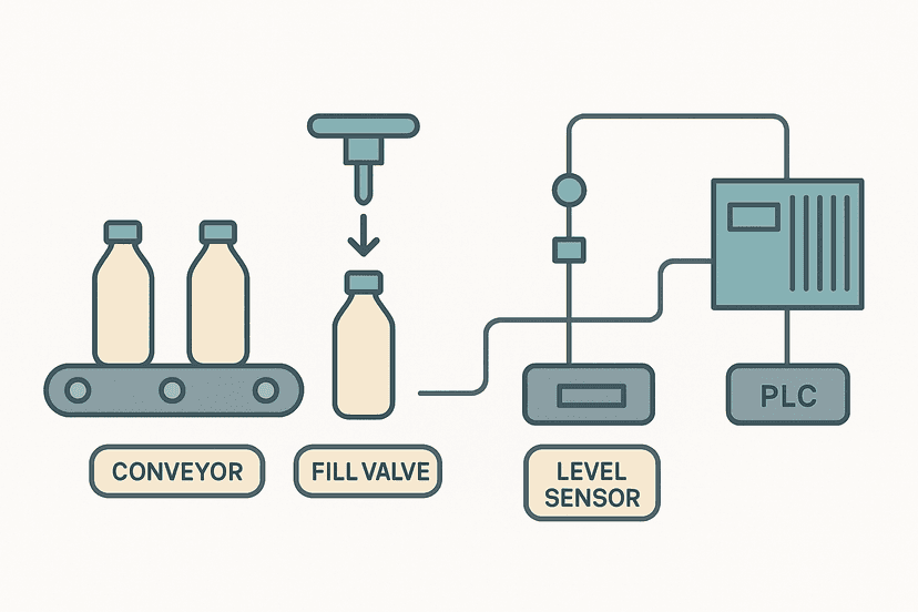
If you're coming from a project like the PLC Bottle Filling Machine exercise, you'll notice the structure is the same: state integer, transition conditions, output map. The car wash is more complex because the gantry moves in two directions and multiple states share the same physical output (GantryFwd appears in States 2, 3, 4 and 5). That shared-output pattern is where beginners write duplicate logic and then wonder why the gantry moves when it shouldn't.
WashState. Output rungs read WashState and drive physical I/O. Mixing the two in one rung makes troubleshooting painful.What You Should Be Able to Do After This
Build this in simulation first. Studio 5000 Logix Designer lets you force I/O tags offline. Simulate GantryAtEnd by forcing it TRUE after you see GantryFwd go TRUE. Step through every state. Then break it: force EStop FALSE in State 4 and verify the brush motor de-energises immediately. If your logic handles that cleanly, you've written sequencer logic that'll hold up in the field.
Was this helpful?