HMI Tag Linking: Mapping PLC Addresses Correctly
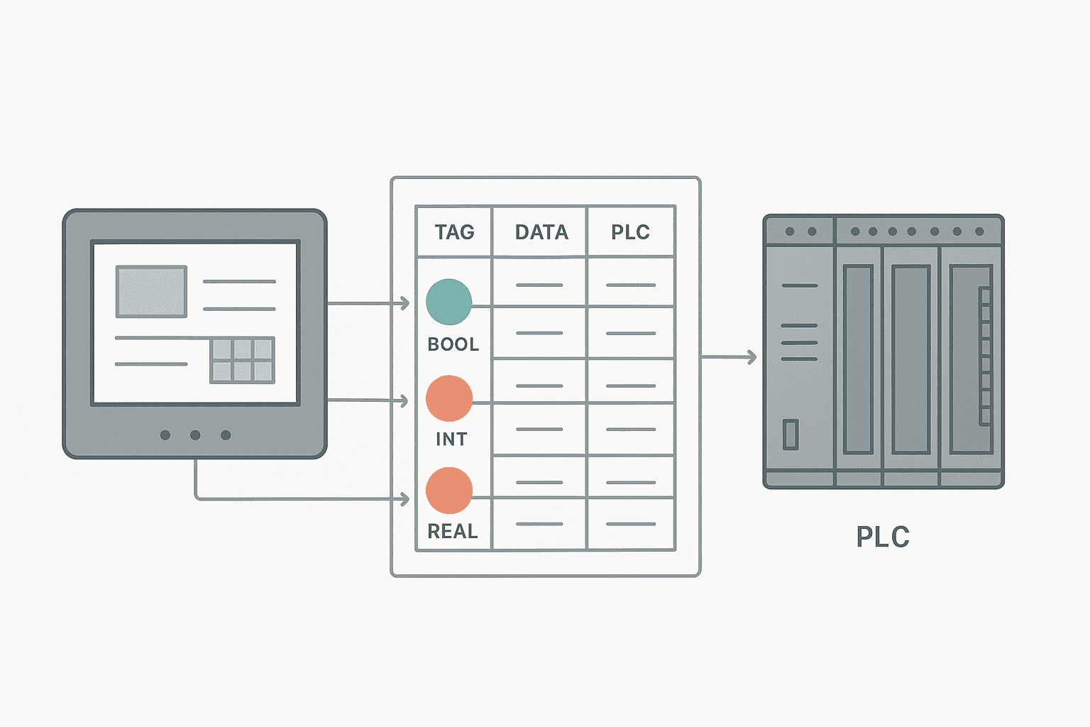
Every number on an HMI screen has to come from somewhere. That somewhere is a tag, and the tag is nothing more than a named pointer to a memory address in the PLC (or, for internal values, in the HMI itself). Get the address right, the data type right, and the polling rate sensible, and the screen reflects reality. Get any one of those three wrong and you end up with a value that is frozen, scaled incorrectly, or completely fabricated. I have seen a pump show 0 RPM on the HMI while running at full speed for two hours before anyone noticed, purely because the tag was pointing at the wrong register.
HMI Tag Linking: Internal vs External Tags
Almost every HMI platform, whether it is Siemens WinCC, Weintek EasyBuilder, Factorytalk View, or a CODESYS VisuOPC panel, splits tags into two categories. Internal tags live entirely in the HMI runtime memory. They hold values that the HMI calculates, uses for screen navigation, or stores locally. External tags, also called connected tags or process tags, point directly at a PLC memory address over the communication driver.
The distinction matters because internal tags do not load your PLC communication at all. If you need a local setpoint that the operator types in and the HMI uses for a display-only calculation, use an internal tag. If the PLC needs to read that setpoint to control a valve, it has to be an external tag written back to the PLC. Mixing these up is one of the most common bugs I see on first-time HMI builds.
PLC Address Mapping: What You Are Actually Pointing At
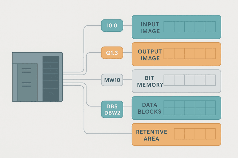
The address you enter in the HMI tag table has to match the PLC memory exactly. This means three things must line up: the address itself, the data type, and the bit-within-word index if you are reading a single bit out of a word.
Address format by platform
| PLC Platform | Typical HMI Address Format | Example |
|---|---|---|
| Siemens S7-1200/1500 (symbolic) | DB number + symbolic path or DBX/DBW/DBD offset | DB1.DBW4 or DB1.Tank_Level |
| Siemens S7-300/400 (absolute) | Memory area + byte offset | MW10, DB5.DBD0, I0.3 |
| Allen-Bradley Logix (tag-based) | Controller tag name or array element | Tank_Level, Conveyor_Speed[2] |
| Allen-Bradley SLC/MicroLogix (file-based) | File type + file number + element | N7:10, F8:2, B3:0/5 |
| Mitsubishi Q/iQ-R | Device type + address number | D100, W10, M200 |
| Omron NJ/NX (symbolic) | Variable name as defined in Sysmac | Tank1_Level_PV |
| Modbus TCP/RTU device | Coil or register number | 40001, 00017, 30005 |
Data Types: Where Silent Errors Live
This is where I see the most silent failures. The PLC stores a value as one data type, and the HMI reads it as another. The communication does not error out. The tag updates happily. The number on screen is just wrong.
Classic example: a Mitsubishi PLC stores a flow rate as a 32-bit floating-point value in D200 and D201 (two consecutive 16-bit registers). The HMI operator sets up the tag pointing at D200 with a 16-bit unsigned integer type. The HMI reads only the low word of the float and displays complete garbage. The fix is to set the HMI tag type to FLOAT32 and confirm that the driver handles the two-register read correctly, including byte and word order.
Common data type mismatches and their symptoms
| PLC Type | Wrong HMI Type | Symptom on Screen |
|---|---|---|
| REAL (32-bit float) | INT or UINT (16-bit) | Nonsense value, often very large or near zero |
| DINT (32-bit signed) | INT (16-bit signed) | Value wraps at 32767 or shows negative unexpectedly |
| BOOL bit in a WORD | WORD or INT | Shows 0 or 1 when the whole word is needed, or always 0 if wrong bit index |
| BCD-encoded integer | Binary INT | Value is wrong by a factor, e.g. 100 shows as 256 |
| UINT (unsigned) | INT (signed) | Values above 32767 appear negative |
Polling Rate and Update Class: Do Not Ignore This
Every HMI tag gets assigned to an update class (sometimes called a polling group or acquisition cycle). This is how often the HMI asks the PLC for a fresh value. Most platforms let you define several classes: say 100 ms, 500 ms, 1 s, and 5 s. You assign each tag to the appropriate class.
The temptation is to put everything on the fastest class. Resist it. A 100 ms poll across 400 tags over a serial Modbus RTU link at 19200 baud will choke the driver. You end up with worse actual update rates than if you had used 500 ms selectively. Fast classes should be reserved for values that genuinely change quickly and that the operator needs to react to: an active fault bit, a fill level during a fast fill cycle, a conveyor speed during commissioning. A weekly batch counter does not need 100 ms updates.
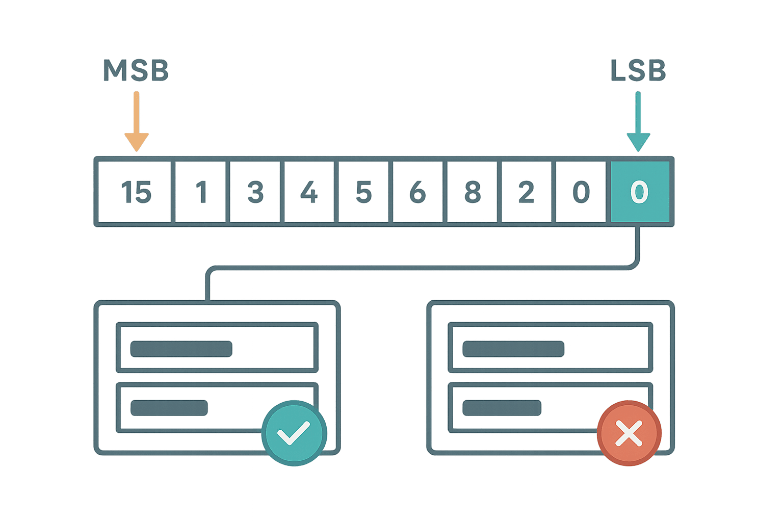
Bit Addressing Inside a Word: The Index Trap
When you need to display individual status bits packed into a 16-bit word (common with older PLCs and Modbus devices), you have to specify the bit index correctly. The trap is that different platforms number bits differently. Siemens numbers bits 0 to 7 within a byte, with bit 0 being the least significant. Allen-Bradley Logix uses zero-based bit indexing on DINT values where bit 0 is also LSB. Modbus coil addresses are independent and do not have this issue.
Where it gets messy is in third-party HMI software reading Mitsubishi or Omron PLCs via Modbus. Some HMI drivers present the bit index as 0 to 15 counting from LSB. Others count from MSB. Check the driver documentation, then verify against a known value: force bit 0 on in the PLC and confirm the HMI shows the correct bit toggling. Do not guess.
Scaling Inside the HMI Tag: Use It Carefully
Most HMI platforms let you apply a linear scaling formula directly in the tag definition: raw PLC value maps to an engineering value. For example, a raw 0 to 27648 from an S7-1200 analog input maps to 0.0 to 100.0 percent. This is convenient, but it creates a hidden layer of math that the next engineer has to find and understand.
My preference is to do the scaling in the PLC and pass the engineering value directly to the HMI as a REAL or scaled integer. That way the PLC program is the single source of truth. If the instrument range changes, you update one place: the PLC code. You do not have to remember to also update the HMI tag scaling. The 4-20 mA scaling formula guide covers the PLC-side math in detail if you need it.
Write-Back Tags: Operator Setpoints Going to the PLC
Read tags are straightforward. Write-back tags, where the operator types a value on the HMI and it goes to the PLC, need extra thought. Three things to get right:
- Limits in the HMI tag: Set minimum and maximum values in the tag definition. This stops an operator entering 9999 when the valid range is 0 to 100. The HMI should reject out-of-range entries before they ever reach the PLC.
- Limits in the PLC too: Do not rely solely on the HMI for range checking. The PLC should clamp or reject out-of-range setpoints independently. HMI tags can be forced via third-party tools or during commissioning with direct writes.
- Write confirmation: For setpoints that affect safety or product quality, add a confirmation dialog in the HMI before the write completes. Most platforms have a built-in confirmation object for numeric entry fields.
Testing Your Tag Map Before Going Live
The only reliable test is a forced-value check for every critical tag. In the PLC, force the tag to a known value (say, 1234 or TRUE), then confirm the HMI shows exactly that value. Then force it to another value and confirm it updates. Do this for every tag that drives operator decisions or alarming. It takes time, but it is the only way to catch address mismatches before startup.
For large projects with hundreds of tags, build a test spreadsheet with the tag name, PLC address, forced test value, and expected HMI display value. Work through it systematically. It sounds tedious but a wrong flow rate on a dosing line or a wrong temperature on a batch reactor is a much worse problem to solve after go-live.
If you are working in TIA Portal and connecting to Siemens panels, the HMI Programming in TIA Portal guide covers the tag connection workflow in detail, including how symbolic linking works between the PLC and WinCC tags.
A Quick Tag Map Checklist
- Confirm the PLC address exists and is the correct memory area (DB, M, I, Q, etc.).
- Match the HMI data type exactly to the PLC data type (BOOL, INT, DINT, REAL).
- Verify bit index if reading individual bits from a word register.
- Assign polling rate based on how fast the value changes and how critical it is.
- Group tags into consecutive address blocks to minimize driver requests.
- Set engineering limits on write-back tags in both the HMI and the PLC.
- Force-test every critical tag with a known value before commissioning.
Frequently asked questions
What is the difference between an internal tag and an external tag in an HMI?
Why does my HMI show a wrong value even though the communication is connected?
How fast should I set the HMI polling rate for process values?
Should I do analog scaling in the HMI tag or in the PLC?
What is the best way to read a single bit from a Modbus holding register in an HMI?
How do I prevent an operator from entering an out-of-range setpoint on an HMI?
Learn this by building it
There is a PLC in this site. It runs a real scan engine, checks your logic against the same tests a working machine would fail, and needs no download and no account.
Open the exercisesFree, no signup, runs in your browser. See all 16 exercises.
Was this helpful?