PLC CPU Faults: How to Diagnose Them Step by Step
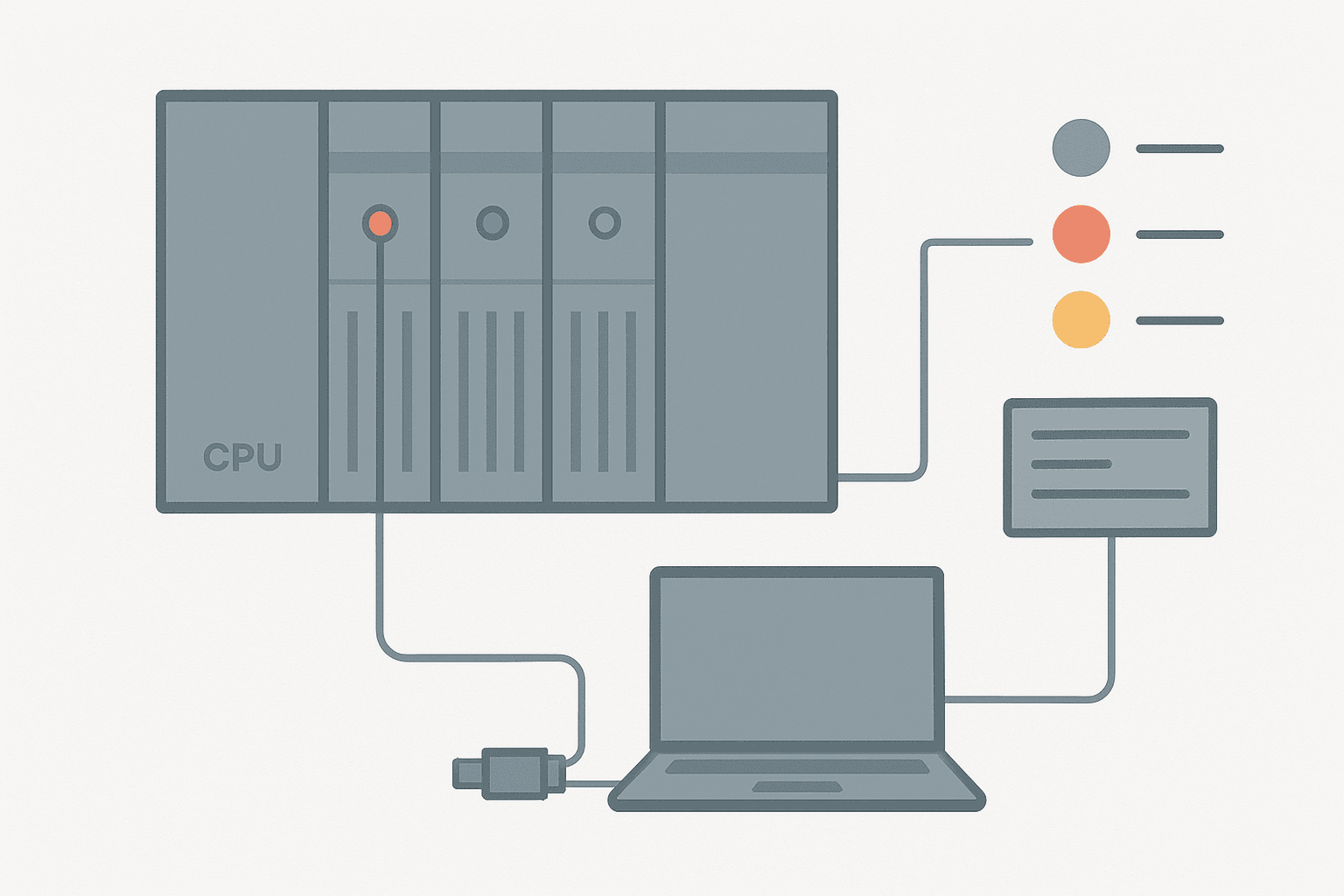
The CPU fault light comes on, the machine stops, and everyone looks at you. It's a situation every automation engineer knows. The wrong move is to clear the fault and restart without reading anything. The right move takes about 10 to 15 minutes and tells you exactly what happened and whether it's safe to restart.
What Is a PLC CPU Fault?
A PLC CPU fault is a condition where the processor detects an error serious enough to halt normal program execution. The CPU stops scanning the user program, forces outputs to a defined fault state (usually de-energized), and sets a fault indicator. Every major PLC platform stores a fault code, a fault type and a timestamp in an internal fault buffer that you can read with the programming software or, on many platforms, directly from the CPU's display.
Step 1: Read the Fault Code Before You Touch Anything
The fault code is your single most valuable piece of information. Do not cycle power, do not turn the key switch, and do not press Clear Faults until you have written it down. On a Siemens S7-1200 or S7-1500 the CPU shows a blinking error LED and TIA Portal's online diagnostics page lists the stop cause under the CPU's "Diagnostics" tab. On a Rockwell Logix controller, open the Controller Properties, go to the "Major Faults" tab and you'll see the fault type, code and the exact rung or routine where execution stopped. Omron NJ/NX controllers surface the error in Sysmac Studio's "Troubleshooting" pane with a plain-English description alongside the error code.
Step 2: Classify the Fault Type
CPU faults fall into a handful of categories. Knowing the category tells you immediately where to look. The table below maps the most common fault types to their root causes:
| Fault Category | Typical Code Range (Logix) | Root Cause to Check |
|---|---|---|
| Watchdog / Scan Overrun | Type 6, Code 1 | Infinite loop, blocking comms instruction, oversized program |
| I/O Module Hardware | Type 4, Code varies | Shorted output, failed module, loose backplane connection |
| Power Supply | Type 1, Code 1 | 24 VDC rail below threshold, capacitor failure in PSU |
| Program / Instruction | Type 6, Code 3-7 | Divide-by-zero, array index out of range, bad data type |
| Firmware / Memory | Type 1, Code 16 | Corrupted program file, failed battery, incompatible firmware |
| Communication | Type 3, varies | Missing device on ControlNet/EtherNet/IP, connection timeout |
Step 3: Check the Power Supply First
I've walked into sites where the team spent two hours swapping CPU modules before someone measured the 24 VDC rail. It was at 19.1 V under load, right on the edge of the CPU's undervoltage lockout. Measure the supply voltage at the CPU terminals with a calibrated meter, not just at the power supply output terminals. Voltage drop across wiring and fuse holders is real, especially in older panels with corroded terminals. You want to see at least 22 V for a nominal 24 V system. If you're sizing a new supply, the post on 24 VDC power supply sizing for control panels covers the load calculation in detail. Also check whether the panel has a solid control panel grounding arrangement, because a floating ground can cause the CPU to see phantom voltages and trigger spurious faults.
Step 4: Isolate Suspected I/O Modules
If the fault code points to a specific rack and slot, that module is your prime suspect. The quickest isolation test: inhibit or disable that module in software (most platforms support this without removing it), then attempt to clear the CPU fault. If the CPU recovers and runs, you've confirmed the module is the problem. If you can't inhibit in software, power down and physically remove the module. Run the CPU without it. Be aware that removing an output module mid-process can have consequences, so always coordinate with operations before pulling hardware.
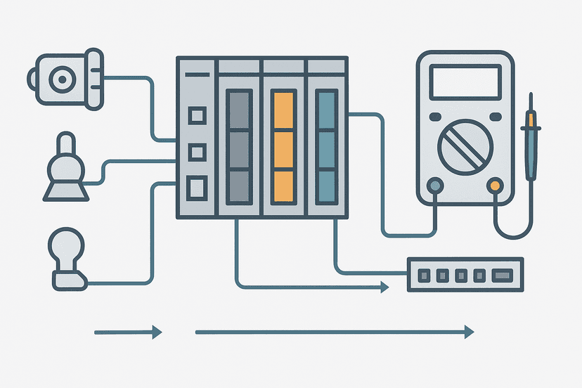
For input faults you can cross-check with a multimeter. The post on PLC I/O fault diagnosis with a multimeter walks through the exact voltage checks for both digital and analog channels. For analog input modules specifically, a broken wire on a 4-20 mA loop can look like a hardware fault to the CPU if the module is configured to generate a channel fault on open-circuit detection. See PLC analog input wiring for 4-20 mA for the wiring details that prevent this.
Step 5: Check for Watchdog and Scan Overrun Faults
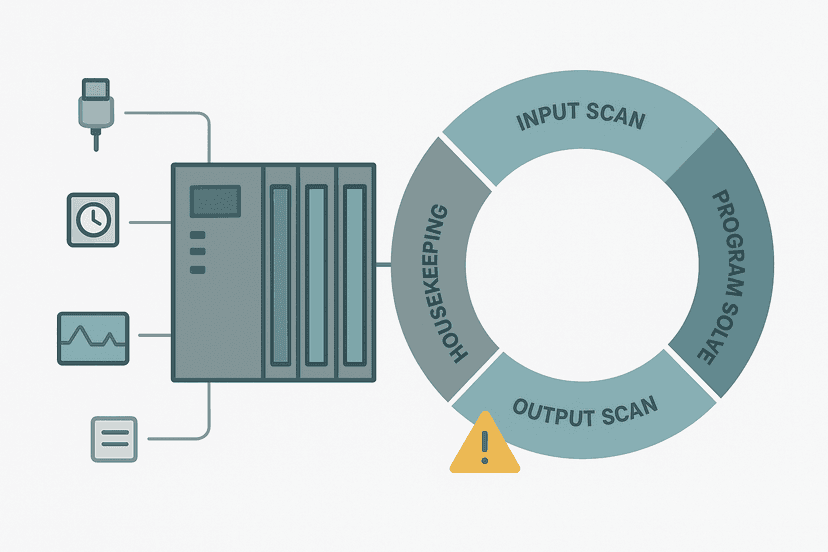
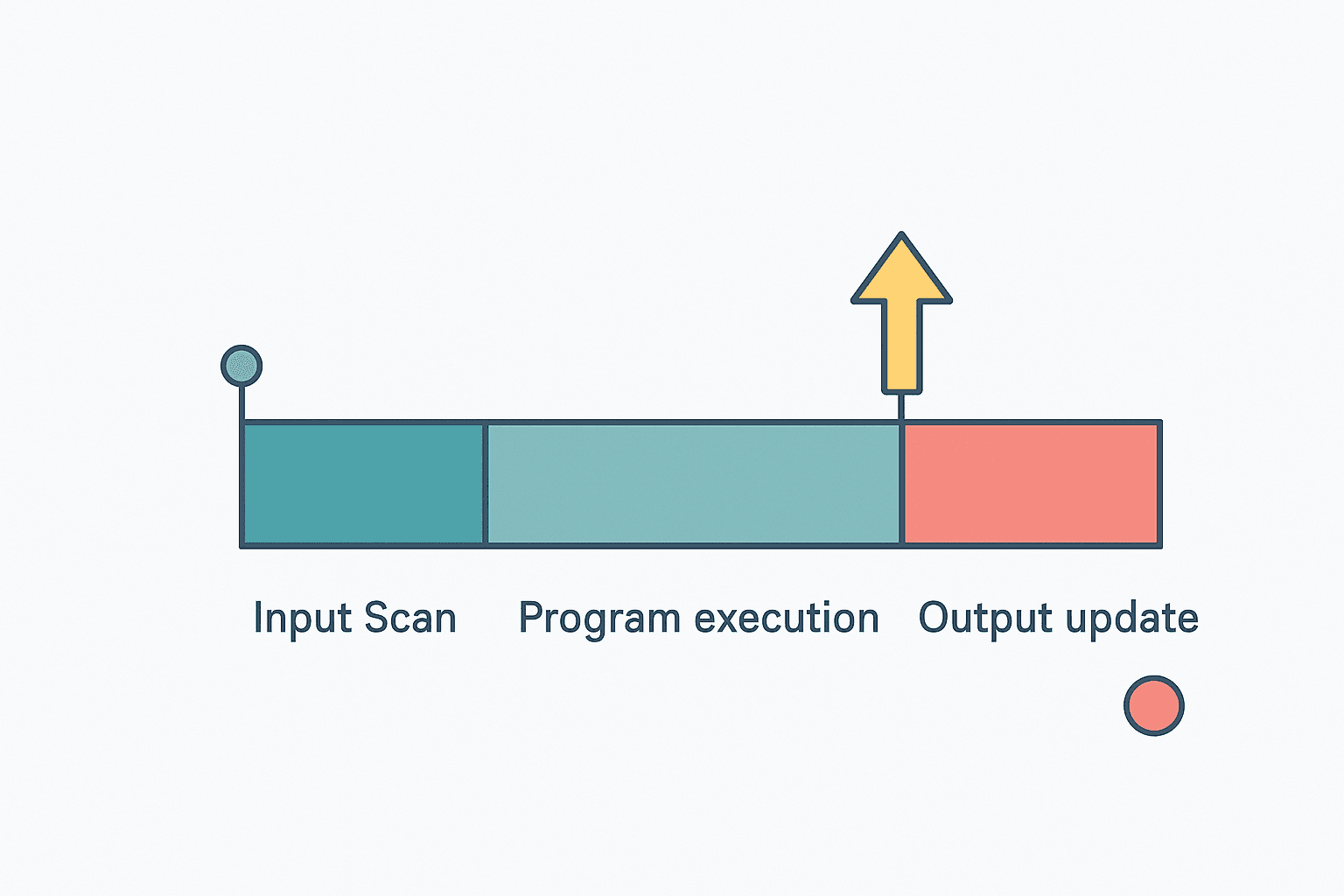
A watchdog fault means the scan took longer than the configured maximum. The usual suspects are a FOR loop without a proper exit condition, a blocking MSG or communication instruction, or a program that grew significantly since the watchdog timeout was last reviewed. On Rockwell Logix, the watchdog is set per task in the task properties (default is 500 ms for a continuous task). On Siemens S7-1200, the maximum cycle time is set in the CPU properties under "Cycle time", defaulting to 150 ms.
Use the platform's online monitoring to watch the actual scan time before it faults again. Rockwell shows "Last Scan" and "Max Scan" in the Controller Diagnostics. Siemens shows cycle time in the online CPU properties. If the scan time is creeping upward over hours or days, something in the program is leaking execution time. The post on PLC scan cycle problems goes deep on exactly this pattern.
Step 6: Check Program-Level Faults (Divide-by-Zero, Array Overrun)
Instruction-level faults are common during commissioning and after recipe or setpoint changes. A divide-by-zero happens when a scaling calculation uses a tag that an operator or HMI set to zero. An array index overrun happens when a recipe select value goes out of range. Both are entirely preventable with range checking. On Logix, the fault message will name the routine and rung. On TIA Portal, the call stack in the diagnostic buffer identifies the exact network and block. Go straight there in the program and add a limit check. The PLC memory and addressing post explains how indirect and indexed addressing creates these vulnerabilities if bounds aren't guarded.
Step 7: Check Battery and Firmware
A low or dead backup battery will not cause an immediate CPU fault while power is on, but it will cause the program to vanish after a power cycle. When the CPU powers up with no program, it faults immediately. Most CPUs have a battery LED or a battery low bit in the status data. Check it during every scheduled inspection. Firmware mismatches are most common after a CPU swap: the replacement unit has different firmware than the original, and the project file refuses to download or runs incorrectly. Always verify firmware revision before swapping hardware. For Siemens S7-1200 specifically, the S7-1200 vs S7-1500 comparison notes the firmware compatibility considerations when replacing hardware across generations.
Step 8: Use Online Monitoring to Confirm the Fix
After you've addressed the suspected root cause, put the CPU back online in Monitor mode before commanding RUN. Watch the scan time, watch the I/O module status bits, and watch any tags that were near the fault point. Give it 5 to 10 minutes at idle and then through a complete machine cycle if it's safe to do so. The post on PLC troubleshooting with online monitoring covers exactly which status bits and diagnostic pages to watch on major platforms. If you're dealing with a communication fault, check whether the post on PROFINET communication loss diagnosis or EtherNet/IP scanner and adapter behavior applies to your network setup.
Common Mistakes That Make CPU Faults Worse
- Clearing the fault without reading the code, then losing the diagnostic information permanently.
- Cycling power as the first response: this clears volatile fault data and sometimes makes the CPU start normally once, masking an intermittent fault that will return.
- Swapping the CPU module before checking the power supply, I/O modules and wiring. Hardware swaps should be last resort, not first.
- Ignoring minor faults in the fault log. A minor fault that fires 50 times a day is telling you something is wrong before it becomes a major fault.
- Not documenting the fault code, time and machine state for the maintenance log. The second occurrence is always easier to diagnose if you recorded the first one.
A Quick Note on Communication-Induced CPU Faults
Communication faults deserve special mention because they're often misread as CPU hardware problems. If a remote I/O device, a drive or a remote rack goes offline and the connection is configured as "required" (the default on most platforms), the CPU will fault. The fix is usually to check the network cable and device, but you also need to decide whether the device being offline should really fault the entire CPU or just raise an alarm. For non-critical devices, setting the connection as "inhibitable" or using a fault routine to handle the loss gracefully is better practice. The post on types of PLC modules explains how remote I/O modules communicate back to the CPU and why a bad backplane or network link looks identical to a hardware module failure.
Keep Learning
CPU fault diagnosis is the high-level skill. The detail work happens at the I/O level and inside the program. Start with PLC I/O fault diagnosis with a multimeter for the hands-on voltage checks, then read PLC scan cycle problems if your fault codes point to timing or watchdog issues. If you're preparing for a technical interview, the PLC troubleshooting interview questions post covers the exact questions you're likely to face on CPU faults, scan overruns and fault recovery procedures.
Frequently asked questions
What causes a PLC CPU to go into fault mode?
How do I clear a PLC CPU fault?
Can a PLC CPU fault cause outputs to stay on?
What does a watchdog fault mean on a PLC?
How do I read PLC fault codes without a laptop?
Is it safe to put a faulted PLC back into RUN mode remotely?
How often should I back up PLC program memory?
Can a bad I/O module cause a PLC CPU fault?
What is the difference between a major fault and a minor fault on a PLC?
Learn this by building it
There is a PLC in this site. It runs a real scan engine, checks your logic against the same tests a working machine would fail, and needs no download and no account.
Open the exercisesFree, no signup, runs in your browser. See all 16 exercises.
Was this helpful?