Types of PLC Modules: I/O, Comms and More
Ask ten engineers what a PLC is made of and most will say 'a CPU and some I/O cards.' That's correct but incomplete. Modern PLC systems are modular by design, and the module you choose for a given signal or function has a real impact on wiring cost, program complexity and long-term reliability. Getting this wrong early in a project is expensive to fix later.
This post covers every major PLC module type you'll run into: what it does, how it fits into the rack, and the gotchas that bite people the first time they spec one. The examples pull from Rockwell CompactLogix, Siemens S7-1200/1500 and generic CODESYS platforms since those are what most engineers actually see day to day.
The PLC Rack: How Modules Fit Together
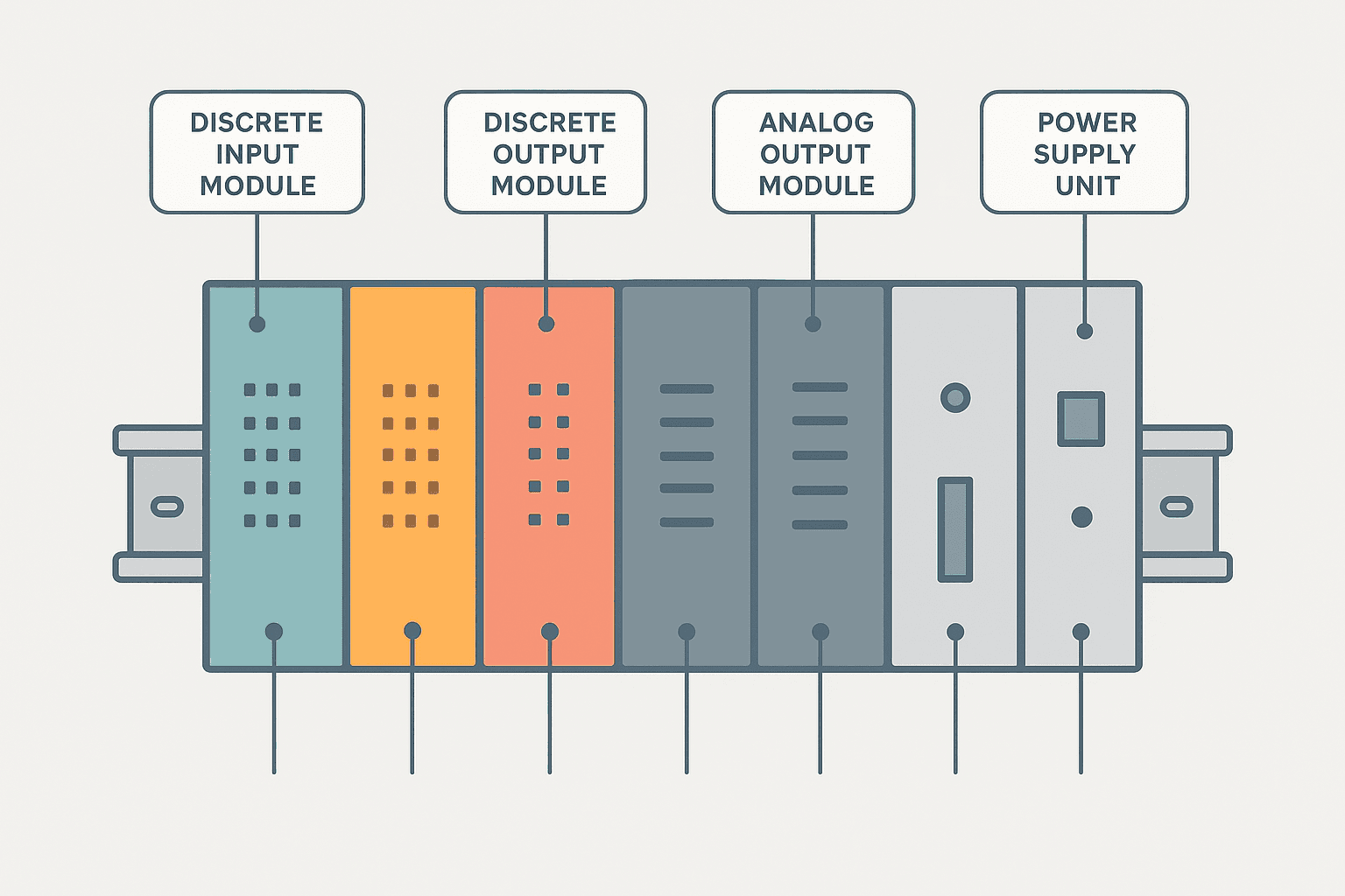
A PLC system is built around a backplane or rail that carries both power and data between modules. The CPU sits in one slot and communicates with every other module through that backplane bus at the start and end of each scan cycle. You configure which module is in which slot in software, and the CPU uses that configuration to know where to read inputs and write outputs.
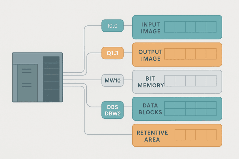
On Rockwell CompactLogix and ControlLogix, modules are added to a chassis and automatically appear in the I/O tree once you add them in Studio 5000. On Siemens S7-1200/1500, you drag them into the device view in TIA Portal. CODESYS-based systems like Beckhoff TwinCAT or Phoenix Contact PLCnext use a similar drag-and-drop device tree. The workflow differs by vendor but the underlying concept is the same: every physical slot maps to a known memory address range that your program reads and writes.
Types of PLC Modules
1. Power Supply Module
The power supply module converts your incoming AC or DC supply (typically 120/240 VAC or 24 VDC) into the regulated 5 VDC or 3.3 VDC the backplane and CPU need. It also usually provides a 24 VDC auxiliary rail you can use to power sensors. On some compact platforms like the S7-1200, the power supply is integrated into the CPU itself. On larger rack systems like ControlLogix, it's a separate module you must size correctly based on the total current draw of all installed modules.
2. CPU / Processor Module
The CPU runs your program, manages the scan cycle, handles communications and coordinates all other modules. It contains program memory (flash or FRAM), data memory (SRAM) and usually one or more built-in Ethernet ports. CPU selection drives everything else: you need enough memory for your program and data, enough network ports for your topology, and enough processing speed for your scan time requirements.
On Rockwell, CPU families range from the MicroLogix 1100 (tiny, fixed I/O) up to the ControlLogix 5580 (large, high-speed motion). Siemens goes from the S7-1200 CPU 1211C up to the S7-1500 CPU 1518F. The 'F' suffix on Siemens CPUs means it includes integrated safety functionality. Always match the CPU to the task, not to the budget alone. Undersizing the CPU is one of the most common mistakes on projects that expand after commissioning.
3. Discrete Input Module (DI)
Discrete input modules read on/off signals: pushbuttons, limit switches, proximity sensors, relay contacts, and similar devices. The module converts the field signal voltage into a logic 1 or 0 that the CPU reads. Typical input voltages are 24 VDC, 120 VAC or 240 VAC, and you must match the module to the field voltage. Mixing a 24 VDC module with a 120 VAC field signal will destroy the module instantly.
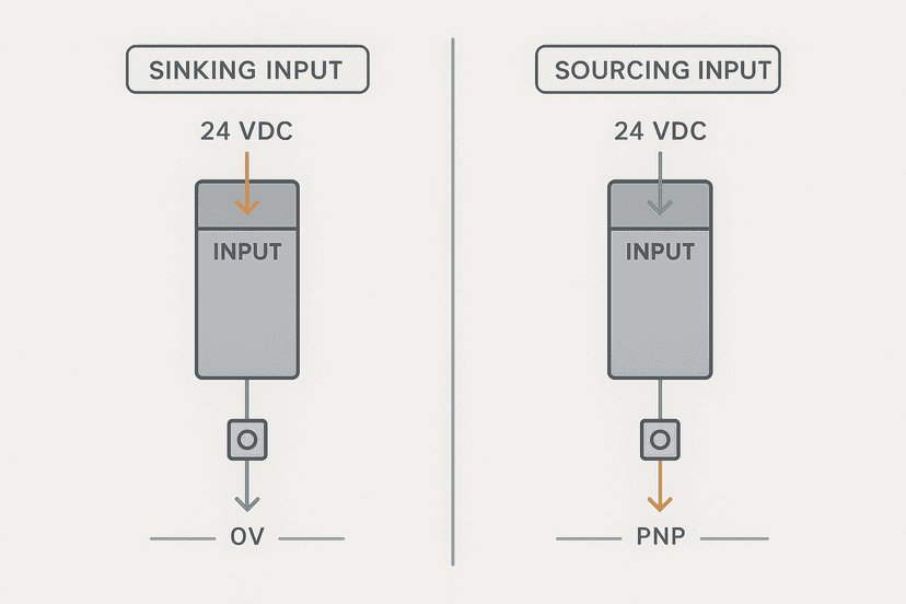
Key specs to check: input impedance (affects minimum current for guaranteed on-state), input filter time (the built-in debounce, typically 1 to 8 ms), sinking vs sourcing compatibility, and whether the module groups inputs into isolated commons or shares a single common. If your sensors are PNP (sourcing), you need a sinking input module. If they're NPN (sinking), you need a sourcing input module. It sounds backwards but that's how it works. The post on sinking vs sourcing PLC I/O covers this in detail.
4. Discrete Output Module (DO)
Discrete output modules switch field devices on and off: solenoid valves, contactors, indicator lights, and small motors. Output types fall into three categories: relay, transistor (solid-state DC) and triac (solid-state AC).
| Output Type | Load Voltage | Switching Speed | Best For | Watch Out For |
|---|---|---|---|---|
| Relay | 24 VDC to 240 VAC | Slow (10-20 ms) | Mixed voltages, inductive loads | Limited cycle life (typically 1 to 10 million ops) |
| Transistor (DC) | 5-30 VDC | Fast (sub-ms) | High-speed outputs, pulse trains, stepper drives | No AC loads; short-circuit protection varies |
| Triac (AC) | 24-240 VAC | Fast (< 1 ms) | AC solenoids, AC contactors | Leakage current can hold contactors on at off-state |
Relay outputs are the most flexible because they handle any voltage and either polarity. But if you're switching a solenoid valve 10 times a minute, eight hours a day, the relay contacts will wear out in under two years. Use transistor outputs for anything that switches frequently.
5. Analog Input Module (AI)
Analog input modules convert a continuous field signal (4-20 mA, 0-10 V, 0-5 V, thermocouple millivolts, RTD resistance) into a raw integer that the CPU can read and scale into engineering units. Resolution is typically 12 to 16 bits. A 16-bit module gives you 65,536 counts across the full range, which is more than enough for most process applications.
Most modern analog input modules are configurable per channel: you select the signal type (current vs voltage vs thermocouple type K/J/T) in software. Some modules handle the scaling internally and give the CPU a value already in engineering units. Others give you a raw count that you scale in your program. Know which one you have before you write your scaling code. If you're doing the scaling yourself in ladder or structured text, the 4-20 mA scaling formula guide has the exact math.
6. Analog Output Module (AO)
Analog output modules convert a CPU integer into a proportional 4-20 mA or 0-10 V signal to drive VFDs, proportional valves, positioners and similar devices. Resolution is again typically 12 to 16 bits. The CPU writes a scaled value (say, 0 to 32,000 counts for 0 to 100% speed) and the module outputs the corresponding current or voltage.
One thing that catches people out: if your program crashes, resets or the CPU goes to fault mode, what does the analog output do? Some modules hold last state, some go to zero, and some go to a configurable safe value. Always check the module's 'fault mode' setting and configure it deliberately, especially on outputs driving actuators or heater elements.
7. Communications Module
Communications modules add network ports that the CPU doesn't already have built in, or provide additional protocol support. Common types include Ethernet modules (for EtherNet/IP, PROFINET, Modbus TCP), serial modules (for Modbus RTU, RS-232, RS-485) and fieldbus modules (PROFIBUS DP, DeviceNet, CANopen).
On a Siemens S7-1500, you'd add a CM 1542-5 module to get a PROFIBUS DP master port. On a Rockwell CompactLogix, you might add a 1769-L30ERM with built-in EtherNet/IP, or a 1769-ASCII module for serial comms to a barcode reader. The key decision is whether the CPU handles the protocol natively or whether you need a dedicated module to offload the comms processing.
8. High-Speed Counter Module (HSC)
Standard discrete input modules have a filter time of 1 to 8 ms, which means they can't reliably read signals faster than about 100 to 500 Hz. For encoder feedback, flow meter pulses or any high-frequency digital signal, you need a high-speed counter module. These modules count pulses in hardware, independent of the PLC scan cycle, at rates from 100 kHz up to 1 MHz or more depending on the module.
HSC modules typically support quadrature encoder input (A, B, Z channels), single-phase counting, and up/down counting. The CPU reads the accumulated count and the module's status at each scan. On Rockwell Logix, the 1756-HSC gives you four 32-bit counters at up to 1 MHz. On Siemens, the S7-1200 CPU has built-in HSC inputs (up to 100 kHz) but you can add an SM 1221 high-speed module for more channels.
9. Motion / Axis Module
Motion modules close the servo loop in hardware, handling position feedback and drive commands at update rates of 250 microseconds to 1 ms, far faster than any PLC scan cycle could achieve. On Rockwell, the 1756-M02AE or the software-based Kinetix EtherNet/IP approach both give you coordinated multi-axis control through PLCopen-style function blocks. On Siemens, the S7-1500T adds technology objects (TOs) for axis control over PROFINET IRT.
You don't always need a dedicated motion module. For simple point-to-point moves over EtherNet/IP or PROFINET, many modern drives handle the position loop themselves and the PLC just sends target positions and monitors status. A dedicated motion module becomes necessary when you need tight multi-axis coordination, electronic gearing or cam profiles.
10. Safety I/O Module
Safety I/O modules are not the same as standard I/O modules, even though they look similar and sit in the same rack. They're certified to IEC 61508 and designed to detect internal faults through diagnostics like cross-checking dual-channel inputs, output short-circuit detection and heartbeat monitoring. On Rockwell, the 1791DS series safety I/O modules communicate over CIP Safety. On Siemens, the ET 200SP F-modules use PROFIsafe. Both require a safety CPU or safety controller to process the safety data.
Never substitute a standard I/O module in a safety-rated circuit just because it's cheaper or immediately available. The diagnostic coverage is completely different and your SIL or PL claim will be invalid.
Choosing the Right Module: A Quick Reference
| Signal / Need | Module Type | Key Spec to Check |
|---|---|---|
| Pushbutton, limit switch, relay contact | Discrete Input (DI) | Input voltage, sinking/sourcing, filter time |
| Solenoid valve, contactor, pilot light | Discrete Output (DO) | Output type (relay/transistor/triac), current rating |
| 4-20 mA transmitter, 0-10 V sensor | Analog Input (AI) | Resolution (bits), input type, isolation |
| VFD speed reference, proportional valve | Analog Output (AO) | Resolution, fault state behavior, load impedance |
| Thermocouple or RTD | Analog Input (AI) - temperature type | Supported sensor types, CJC accuracy |
| Encoder, flow pulse, high-freq digital | High-Speed Counter (HSC) | Max count rate (Hz), quadrature support |
| Servo axis, multi-axis coordinated motion | Motion/Axis Module | Axis count, update rate, feedback type |
| E-stop, safety gate, light curtain | Safety I/O Module | SIL rating, PROFIsafe/CIP Safety support |
| Modbus RTU, RS-485, serial device | Communications Module | Protocol, baud rate, isolation |
| PROFIBUS DP, DeviceNet, CANopen | Fieldbus Master/Slave Module | Protocol version, node count limit |
Fixed vs Modular PLC Architectures
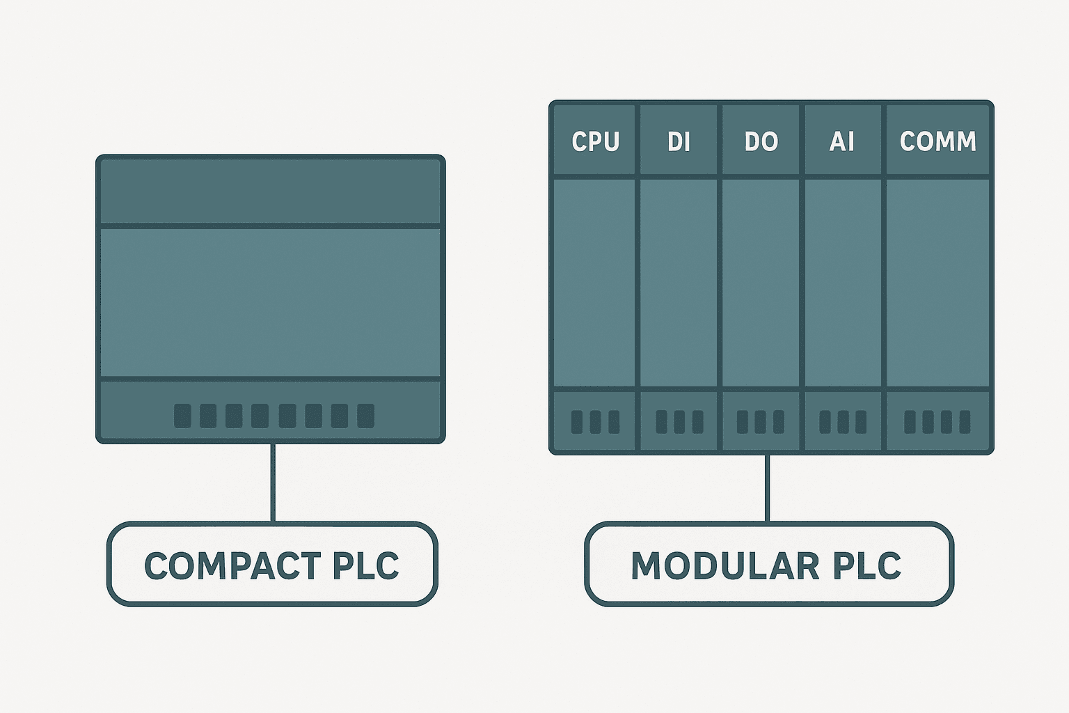
Not every PLC is modular in the full rack sense. Fixed or compact PLCs (like the Siemens S7-1200 CPU 1211C or Allen-Bradley Micro820) have I/O built directly into the CPU housing. You can't remove or replace individual I/O points. They're cheaper for small applications but you're stuck with whatever I/O count and type came on the unit, plus whatever expansion modules the manufacturer supports.
Modular systems like the S7-1500, ControlLogix or Beckhoff CX series let you build exactly the I/O mix you need. You pay more per I/O point but you get flexibility, easier fault isolation (pull out a faulty module and swap it without rewiring) and the ability to expand the system later without replacing the CPU.
Remote I/O: Distributed Module Architectures
When field devices are spread over a large machine or plant, running individual home-run cables back to a central rack gets expensive fast. Remote I/O drops solve this by placing I/O modules physically close to the field devices and communicating with the main CPU over a single network cable. Rockwell uses EtherNet/IP with the POINT I/O and Flex I/O families. Siemens uses PROFINET with ET 200SP and ET 200MP. Beckhoff uses EtherCAT with EK1100 coupler-based remote I/O.
The module types are the same (DI, DO, AI, AO, HSC, safety) but they sit in a remote adapter or coupler instead of the main rack. The only real difference from a programming standpoint is that you configure a network connection to the remote drop, and the I/O addresses appear under that connection in your project tree. Latency is a real consideration for time-critical signals: a remote I/O drop over EtherNet/IP adds roughly 1 to 4 ms of round-trip latency per requested packet interval.
One Ladder Example: Analog Input Module Fault Detection
Most analog input modules expose a channel fault bit in their status data. The example below latches an HMI alarm any time the module reports a fault on channel 0 (open-circuit, over-range or under-range on a 4-20 mA transmitter) and requires an operator acknowledgement after the fault clears before the alarm resets. This is a real, frequently needed pattern that has nothing to do with motor start/stop.
Analog Input Module Channel Fault Alarm with Ack (Studio 5000 / Logix). Ladder logic (3 rungs): Rung 0: examine if AI_Mod:I.Ch0Fault is on (XIC), then examine if AI_Ch0_FaultRise is on (XIC), then latch output AI_Ch0_FaultLatch (OTL). Rung 1: examine if AI_Ch0_FaultLatch is on (XIC), then examine if AI_Mod:I.Ch0Fault is off (XIO), then examine if HMI_AI_FaultAck is on (XIC), then unlatch output AI_Ch0_FaultLatch (OTU). Rung 2: examine if AI_Ch0_FaultLatch is on (XIC), then energize output HMI_AI_Ch0_AlarmActive (OTE). Rung 1: rising edge of the module channel fault bit latches the alarm. Rung 2: the latch clears only when the fault is gone AND the operator has pressed the HMI acknowledge button, preventing a brief fault from self-clearing silently. Rung 3: drives the HMI alarm indicator. AI_Mod:I.Ch0Fault is the channel 0 fault status bit exposed by a 1769-IF4 or similar Logix analog input module.
Common Mistakes When Specifying PLC Modules
- Mixing DC sinking and DC sourcing modules on the same common rail without checking compatibility.
- Using relay output modules on high-cycle applications like solenoid valves that switch every few seconds.
- Forgetting to account for the module's own power consumption when sizing the backplane power supply.
- Trying to read a thermocouple on a standard 0-10 V analog input module.
- Specifying a standard I/O module in a safety loop because it was 'cheaper and available'.
- Not checking the module's fault state configuration on analog outputs before commissioning.
- Adding a remote I/O drop on a legacy ring topology without accounting for the added latency on time-critical signals.
Frequently asked questions
What is the difference between a discrete and analog PLC module?
Can I mix relay and transistor output modules in the same PLC rack?
Do I need a special module for reading encoders on a PLC?
What happens to analog outputs if the PLC goes into fault mode?
What is a remote I/O module and when should I use one?
Can I use a standard I/O module in a safety circuit?
Learn this by building it
There is a PLC in this site. It runs a real scan engine, checks your logic against the same tests a working machine would fail, and needs no download and no account.
Open the exercisesFree, no signup, runs in your browser. See all 16 exercises.
Was this helpful?