NO vs NC Contacts in PLC Ladder Logic: Full Breakdown
Normally open and normally closed contacts trip up engineers at every experience level. Not because the concept is hard, but because there are two completely separate layers: the physical device wired in the field and the software instruction sitting in your ladder rung. Conflating them is one of the most reliable ways to wire a machine that does exactly the opposite of what you intended.
What Do Normally Open and Normally Closed Mean in a PLC?
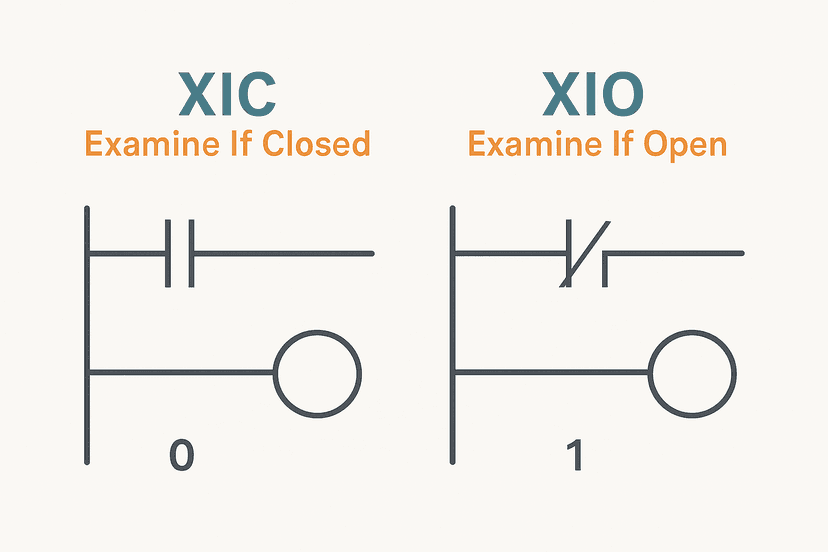
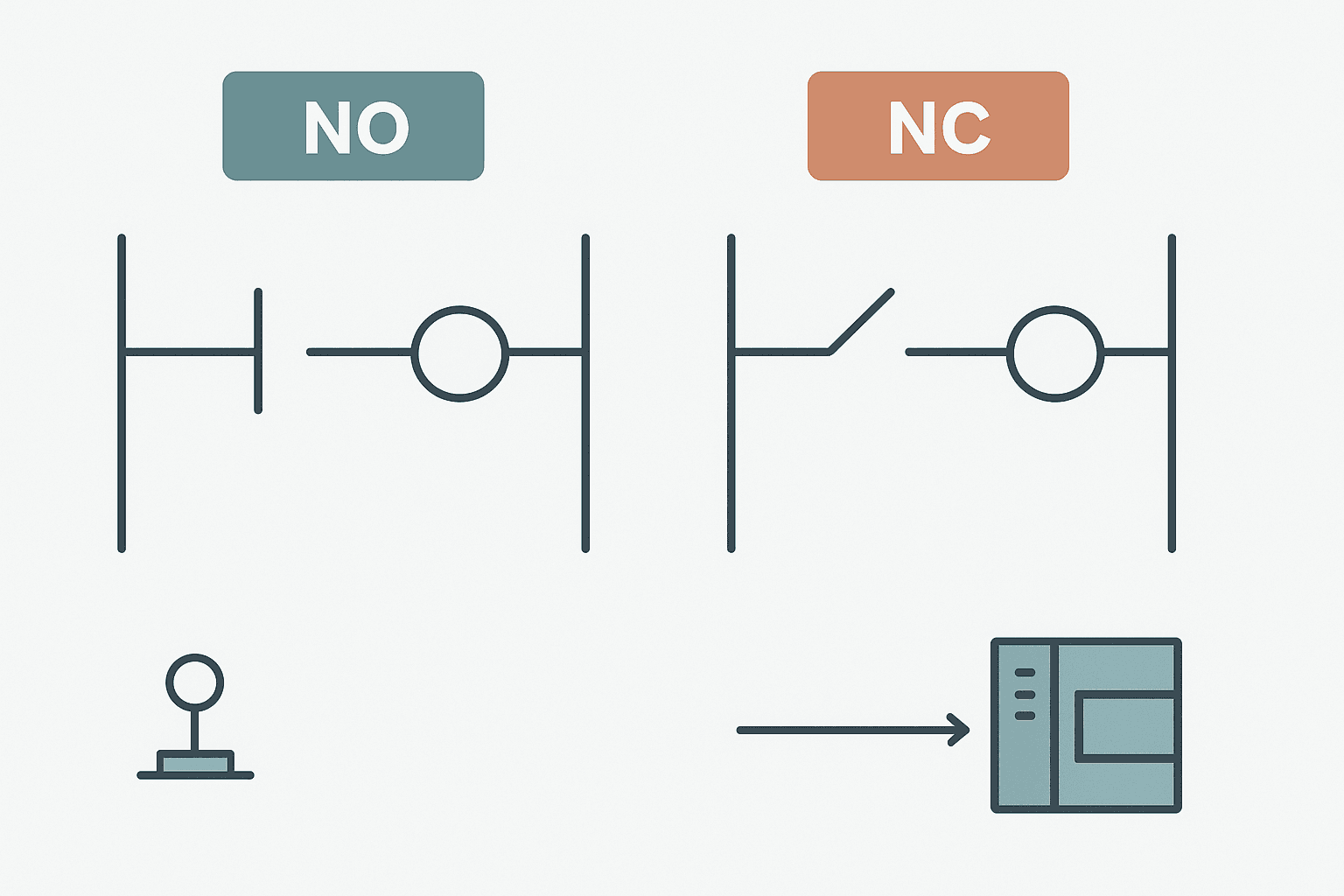
A normally open (NO) contact in PLC ladder logic passes power (evaluates true) when the associated bit in controller memory is 1. A normally closed (NC) contact passes power when that same bit is 0. In Rockwell Studio 5000 these are the XIC and XIO instructions. In Siemens TIA Portal they are the standard contact and the negated contact. The instruction describes the bit state required for the rung to conduct, nothing more. It does not tell you anything about how the field device is physically wired.
The Two Layers You Must Keep Separate
Every input in a PLC system has two distinct properties that interact to produce the bit state the CPU reads. Mixing them up is where confusion breeds.
- Layer 1: Physical contact type. The field device itself (pushbutton, limit switch, relay contact, proximity sensor output) is either physically NO or NC in its de-energised, unpressed, or non-actuated state.
- Layer 2: Software instruction. The XIC or XIO instruction in your rung evaluates the bit that the input module writes based on the voltage it sees. This is purely a software statement about bit state.
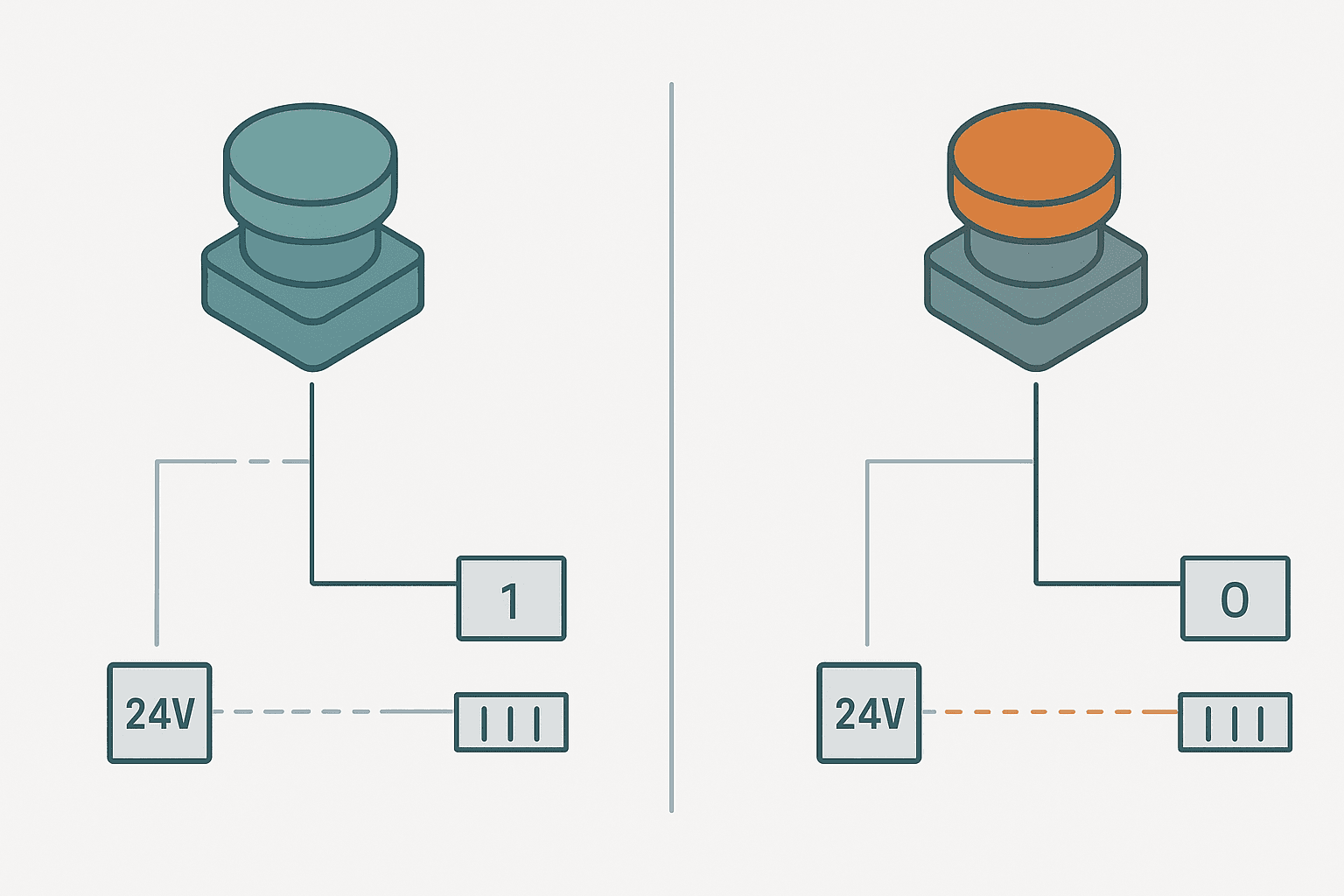
The bit that the input module writes depends on the combination of both layers. A physically NC switch wired to an input, with no actuation, holds the input at 24 VDC, so the module writes a 1 to that bit. A physically NO switch in the same state holds the input at 0 VDC, so the module writes a 0. Once you know the bit state, the XIC or XIO instruction determines whether the rung conducts.
XIC vs XIO: The Rockwell View
If you have already read the post on XIC vs XIO ladder logic contacts, you know the mechanics. To summarise briefly: XIC (Examine If Closed) passes when its tag bit is 1, XIO (Examine If Open) passes when its tag bit is 0. Neither instruction cares whether the physical device is wired NO or NC. It only evaluates the current state of the bit.
The same principle applies in TIA Portal, CODESYS, Omron CX-Programmer and every other IEC 61131-3 compliant tool. The symbol differs by vendor but the logic is identical. If you are new to Siemens and want a parallel reference, the S7-1200 first program walkthrough shows exactly where these contact instructions appear in the Siemens environment.
Truth Table: All Four Combinations
| Physical contact type | Actuated? | Input bit state | XIC result | XIO result |
|---|---|---|---|---|
| NO | No (at rest) | 0 | False (no power flow) | True (power flows) |
| NO | Yes (pressed) | 1 | True (power flows) | False (no power flow) |
| NC | No (at rest) | 1 | True (power flows) | False (no power flow) |
| NC | Yes (pressed) | 0 | False (no power flow) | True (power flows) |
Why the Wiring Choice Matters for Safety
The most common real-world reason to choose NC wiring is fail-safe detection. If a cable breaks or a terminal comes loose, the input bit drops to 0. If your logic uses an XIC on that bit to allow a motion or output, a broken wire automatically removes the enable condition. The machine stops safely without any fault detection logic on your part. This is exactly why E-stops, guard doors and safety gates are almost always wired NC to a PLC input, even when a dedicated safety relay handles the power-cut path. The emergency stop circuit wiring guide covers the hardware side of that in detail.
Sensor Wiring: NO, NC and the PLC Input Bit
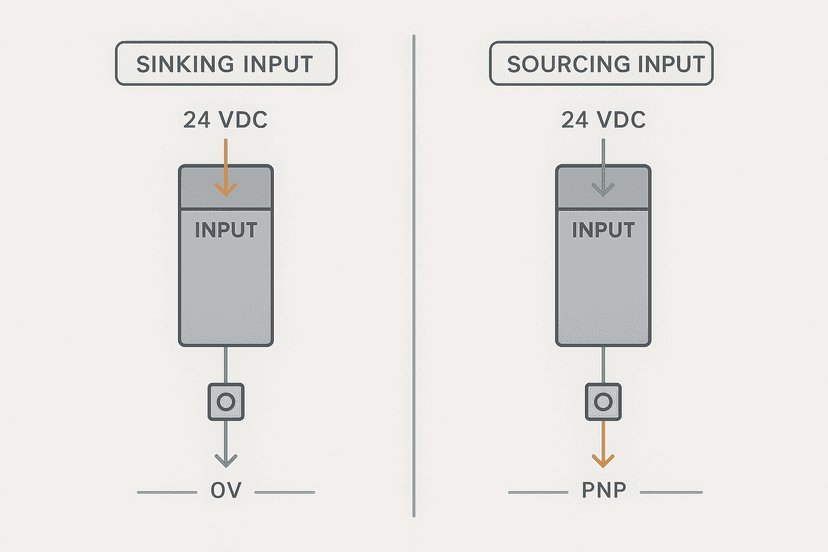
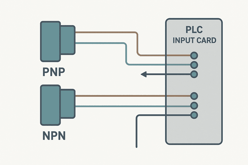
Discrete sensors (inductive, capacitive, photoelectric) add another wrinkle: they can source or sink current depending on wiring, and many have both NO and NC output terminals. The output signal at the sensor terminal determines the voltage at the PLC input terminal, which determines the bit state. If you are using a 3-wire PNP sensor, the output goes high (sourcing 24 VDC) when the target is detected and the sensor output is NO. That drives the PLC input high, writing a 1 to the bit. An XIC on that bit passes when the target is present. Swap to the NC terminal of the same sensor and the logic inverts entirely. The 3-wire PNP and NPN sensor wiring guide covers this with wiring diagrams, and if you are still sorting out whether your module sinks or sources, sinking vs sourcing PLC I/O is worth a read first.
A Real-World Gotcha From the Field
On a conveyor commissioning job a few years ago, we had a jam-detection limit switch wired NC (as specified on the drawing) and an XIO contact in the rung to trigger an alarm when the bit went low. The alarm kept firing at random. Turned out the switch body had a loose mounting bolt and was vibrating slightly on the conveyor frame, intermittently breaking the NC contact. Because the wiring was NC, any brief mechanical bounce looked like a jam event. We swapped to a proximity sensor on an NO output, used XIC for the alarm trigger, and the false alarms stopped. The lesson: NC wiring is safer against open-circuit faults, but it is also sensitive to any event that physically opens the circuit, including mechanical vibration. For intermittent sensor faults like this one, always check the physical mounting before assuming an electrical fault.
Normally Closed Contacts in Interlock Logic
NC contacts in ladder logic (XIO instructions, not physically NC devices) are used constantly in interlocks. A fault latch bit, a stop command, an overtemperature signal: all of these are typically represented as XIO contacts in the permissive chain for an output. The rung reads naturally as 'motor runs if start is pressed AND no stop AND no fault'. The ladder logic interview questions article covers this pattern in depth if you want practice questions around it.
Dual-Zone Conveyor Enable: NO Position Confirm with NC Fault Guard. Ladder logic (4 rungs): Rung 0: examine if Zone1_PartPresent is on (XIC), then examine if Zone2_PartPresent is on (XIC), then examine if Conveyor_FaultLatch is off (XIO), then examine if Estop_Active is off (XIO), then energize output Conveyor_Enable (OTE). Rung 1: examine if Conveyor_Enable is on (XIC), then examine if HMI_StartCmd is on (XIC), then latch output Conveyor_Run (OTL). Rung 2: examine if HMI_StopCmd is on (XIC), then unlatch output Conveyor_Run (OTU). Rung 3: examine if Conveyor_Run is on (XIC), then energize output Conveyor_Drive_Out (OTE). Zone1_PartPresent and Zone2_PartPresent are XIC contacts, representing NO-wired inductive sensors that go high when a part is confirmed in position. Conveyor_FaultLatch and Estop_Active are XIO contacts: both bits are 0 in normal operation, so XIO passes freely. Any fault or E-stop sets those bits to 1, which immediately opens the XIO contacts and drops Conveyor_Enable regardless of the start latch state.
The diagram above evaluates one scan. Run these exact rungs on a real scan cycle to watch the latching and the timers behave.
Run this in the simulatorCommon Mistakes and How to Avoid Them
- Assuming the instruction matches the device. A pushbutton labelled NC on its datasheet does not mean you must use an XIO instruction. Trace the bit state first.
- Double-inversion. Wiring a physically NC device and then using an XIO instruction gives you the same logic as a NO device with XIC. It works, but it is confusing to the next engineer. Pick one inversion point and stick to it.
- Ignoring module power loss. If 24 VDC to the input module drops, all bits go to 0. XIO contacts on those bits all pass. Map out what your outputs do in that scenario.
- NC wiring without a current-limiting path check. A short to 0 V on a line powering an NC-wired device holds the input low permanently. This can mimic the device being actuated. Check with a multimeter at the terminal, not just in the PLC online view. The PLC I/O fault diagnosis guide covers exactly this test procedure.
- Forgetting to update the wiring diagram when you invert logic in software. The physical diagram should reflect reality. If the device is wired NO, the symbol on the drawing should show NO, regardless of which instruction you use in ladder.
Siemens, CODESYS and Other Platforms
In TIA Portal, the NO contact symbol is two vertical bars with no extra mark. The NC contact adds a diagonal slash. The evaluation logic is identical to XIC and XIO: NO passes when the tag is true, NC passes when it is false. If you are working in CODESYS or Beckhoff TwinCAT, the IEC 61131-3 standard defines the same two contact types with the same graphical symbols. The 5 types of PLC programming languages post gives a broader view of how ladder fits alongside ST, FBD and SFC if that context is useful.
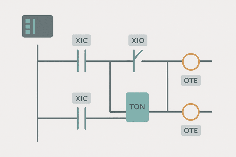
For Siemens-specific ladder work, the S7-1200 timers in TIA Portal article shows contact instructions being used alongside TON and TOF blocks, which is a realistic look at how NO and NC contacts appear in a real program. The structured text in TIA Portal guide also shows how the same NO/NC logic translates when you leave ladder entirely.
Quick Decision Guide
| Situation | Physical wiring | PLC instruction |
|---|---|---|
| Start pushbutton, momentary run command | NO | XIC |
| Stop pushbutton, safety-critical | NC | XIC (bit is 1 at rest, 0 when pressed) |
| E-stop, fail-safe required | NC | XIC (drop to 0 on actuation or wire break) |
| Proximity sensor, detect part present | NO | XIC |
| Guard door open alarm (safe = closed) | NC | XIC (bit 1 = door closed = safe) |
| Fault latch bit in software interlock | N/A (internal bit) | XIO (passes when no fault) |
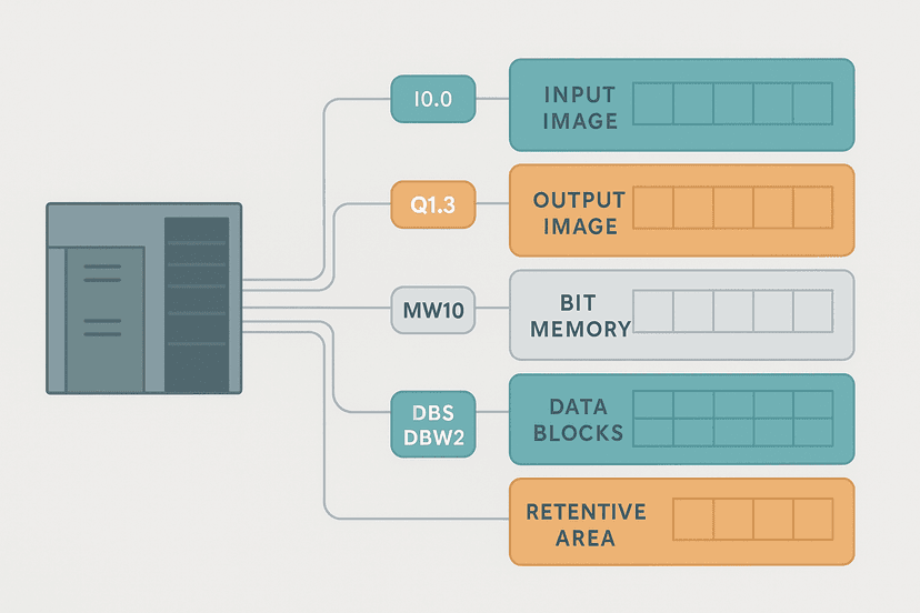
When you are wiring up input modules, the PLC analog input wiring guide and the sinking vs sourcing explanation are useful companions: they cover the electrical details that sit underneath the bit state you are reasoning about here. For a broader look at how PLC addressing and memory work together with these bit states, PLC memory and addressing explained fills in the gaps.
What to Read Next
If this article cleared up the hardware-software split, the next step is understanding exactly how XIC and XIO behave at the instruction level across different Rockwell processor families: XIC vs XIO: Ladder Logic Contacts Explained goes deeper on the instruction mechanics. From there, ladder logic interview questions and real answers will test your understanding with the kind of scenarios you will see on a commissioning job or a technical interview. And if you want to see NO and NC contacts working inside a full program, the PLC bottle filling machine project uses both types in a realistic sequence.
Frequently asked questions
What is the difference between a normally open and normally closed contact in a PLC?
Does a normally closed PLC contact mean the field switch must be wired NC?
Why are E-stops wired normally closed to PLC inputs?
What is XIC and XIO in Allen Bradley ladder logic?
Can I use a normally closed contact on a proximity sensor input?
What happens to a normally closed PLC contact when the input module loses power?
How do I decide whether to use NO or NC wiring for a limit switch?
Is there a normally closed equivalent in Siemens TIA Portal ladder?
Why does my NC wired sensor show the wrong state in the PLC?
Now build it
You have just read about XIO and XIC. Reading a rung and making one behave are different skills, and the second one is the job.
Start / Stop Circuit
Beginnerabout 10 minThe first circuit every controls engineer learns: a motor that starts on a button press, keeps running when the button is released, and stops on a stop button, with stop always winning.
Build this rungFree, no signup, runs in your browser. See all 16 exercises.
Was this helpful?