PLC Troubleshooting Interview Questions: Real Answers
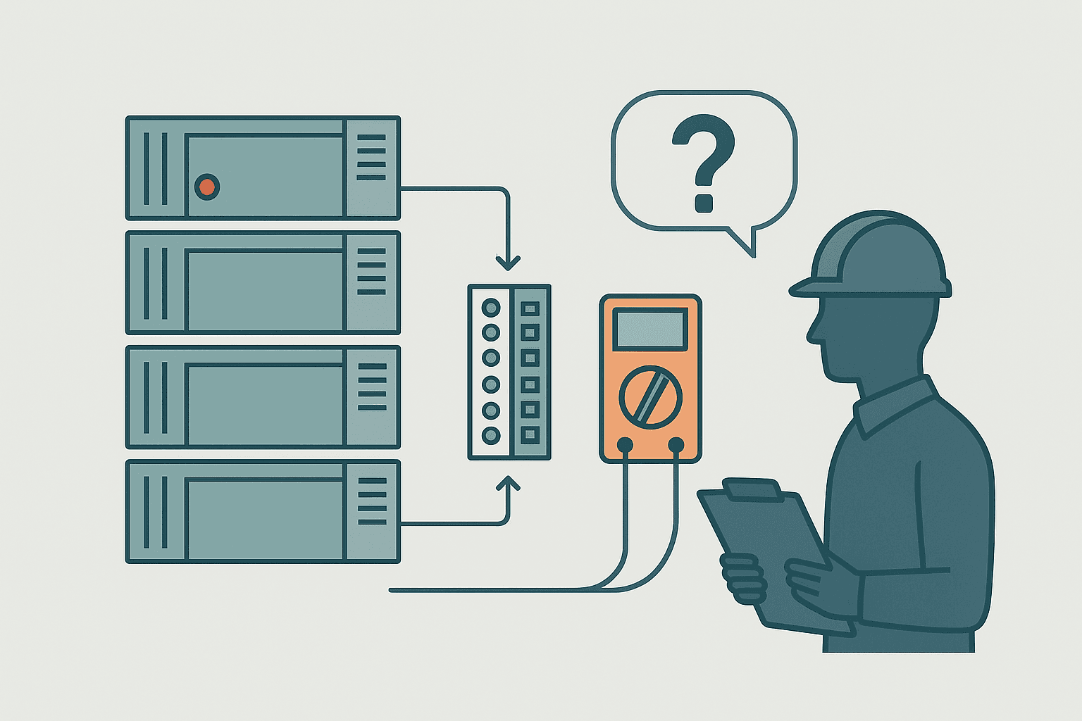
PLC troubleshooting interview questions separate candidates who have genuinely been on the floor from those who have only read manuals. Interviewers know this, so they push past theory fast. They want to hear how you think when a machine is down, a shift supervisor is staring at you, and the fault makes no obvious sense.
What Are PLC Troubleshooting Interview Questions?
PLC troubleshooting interview questions test a candidate's ability to systematically diagnose and fix faults in programmable logic controller systems. They cover hardware failures, program logic errors, I/O wiring faults, analog signal problems and communication losses. Strong answers demonstrate a structured diagnostic method, knowledge of specific tools, and real examples from past jobs.
Why Interviewers Weight Troubleshooting So Heavily
Programming a PLC from scratch is a trainable skill. Keeping a production line running when something breaks at 2 AM is a different matter entirely. Experienced hiring managers know the difference, and they use fault-diagnosis questions as a filter. I've sat on both sides of that table, and the candidates who struggled were almost always the ones who jumped straight to "swap the module" without checking the basics first.
A solid answer always shows a structured approach: eliminate the obvious before going deep. Start at the field device, work toward the PLC, then look at the program. That direction alone signals competence.
The 20 PLC Troubleshooting Interview Questions (With Real Answers)
1. Walk me through your first steps when a machine goes down and you don't know why.
Start with safety: confirm it is safe to approach and that the machine is in a known state. Then check the HMI or operator panel for any active alarms. Connect to the PLC online and look at the diagnostics buffer for the most recent fault code and timestamp. Don't touch anything yet. Read the error, understand what it claims, and then verify it physically. Rushing to reset a fault before understanding it wastes time and can mask the root cause.
2. A digital input shows ON in the PLC but the physical sensor is OFF. What do you suspect?
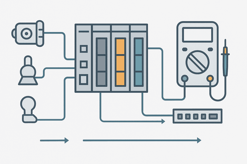
The most common causes are a wiring short between the input terminal and the 24 V supply rail, a failed input channel stuck high, or a leakage current from a solid-state sensor holding the input above the threshold. Measure the actual voltage at the input terminal with a multimeter. If it reads 24 V with the sensor disconnected, you have a short or a wiring error. If it reads 1 to 3 V and the input is still showing ON, the input card threshold may be too low or the sensor is leaking enough current to trigger it. See the guide on PLC I/O fault diagnosis with a multimeter for the exact test procedure.
3. How do you use online monitoring to isolate a logic fault?
Connect in online mode and navigate to the rung that drives the suspect output. Watch which contact in the rung is open when it should be closed. That contact is your next lead: check whether its tag is driven by another rung, a function block, or comes directly from a physical input. Keep tracing upstream. This is exactly the method covered in PLC troubleshooting with online monitoring, and it works across every platform.
4. Explain the PLC scan cycle and how a long scan time causes problems.
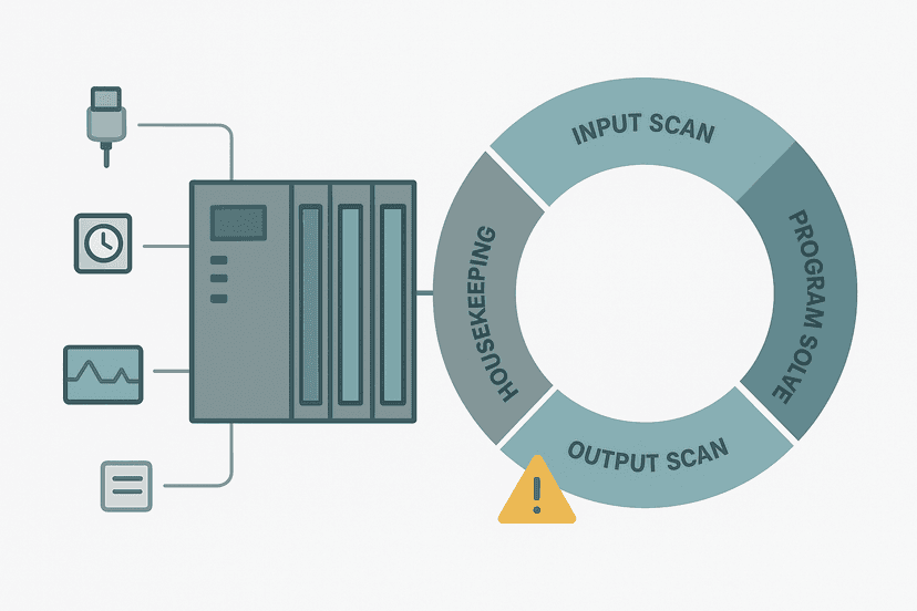
Each scan: read all inputs into the image table, execute every rung of logic from top to bottom, write the output image table to the physical outputs, then service communications and housekeeping. A typical scan runs 1 to 20 ms. If scan time grows, a high-speed sensor pulse shorter than one scan can be missed entirely, and outputs that must respond within tight timing windows will lag. The PLC scan cycle troubleshooting guide covers how to profile and fix runaway scan times.
5. A 4-20 mA pressure transmitter reads full scale on the PLC even though the process pressure is normal. What do you check?
First, measure the loop current with a multimeter in series. If it reads 20 mA, the transmitter is genuinely sending full scale: suspect a failed transmitter, a blocked impulse line, or a misconfigured range. If the measured current is normal (say, 10 mA for mid-range pressure) but the PLC still shows full scale, the fault is in the analog input card, the wiring, or the scaling. Check the raw count register directly. The 4-20 mA scaling formula guide explains how raw counts map to engineering units and where errors creep in.
6. What's the difference between a sinking and sourcing input, and why does it matter for fault-finding?
A sinking input expects the field device to pull the input terminal to common (0 V). A sourcing input expects the device to push the terminal to supply voltage (24 V). Connecting a PNP sensor to a sinking input works. Connecting an NPN sensor to a sourcing input works. Cross those and you'll get no signal, or a permanently ON input. This is one of the most common commissioning faults I've seen on sites that mix sensors from different vendors. The sinking vs sourcing I/O guide and the PNP vs NPN sensor wiring post both cover this thoroughly.
7. An output module has a blown fuse on one group. How do you find the cause before replacing it?
Before fitting a new fuse, identify every output in that group and check each field device for a short circuit or a wiring fault. Disconnect the field wiring from the module terminals, fit the new fuse, and power up. If the fuse holds with wiring disconnected, reconnect one output at a time until it blows again. That isolates the shorted circuit. Never just replace a fuse and hope: you'll blow the next one in minutes. The types of PLC modules guide explains how group fusing is typically arranged.
8. How do you troubleshoot a PROFINET device that drops off the network intermittently?
Intermittent drops are almost always physical layer problems: a connector not clicked fully into the M12 port, a cable routed near a VFD without shielding, or a switch port with auto-negotiation fighting the device. Check the switch port error counters: high CRC error counts confirm a signal integrity problem, not a configuration issue. The PROFINET communication loss diagnosis guide walks through both the hardware checks and the TIA Portal diagnostic buffer reads you need.
9. What is a memory addressing fault and how do you reproduce it safely?
On older PLCs and some current platforms, writing outside a valid array index or using an indirect address pointer that has gone out of range can corrupt adjacent memory or trip a major fault. To reproduce safely, use offline simulation mode or a test PLC, never a live machine. Check every array access in the program against the declared array length, and watch pointer values in online mode before downloading to the real system. The PLC memory and addressing post covers how different platforms handle out-of-bounds accesses.
10. A TON timer in your program never reaches its preset. What could cause that?
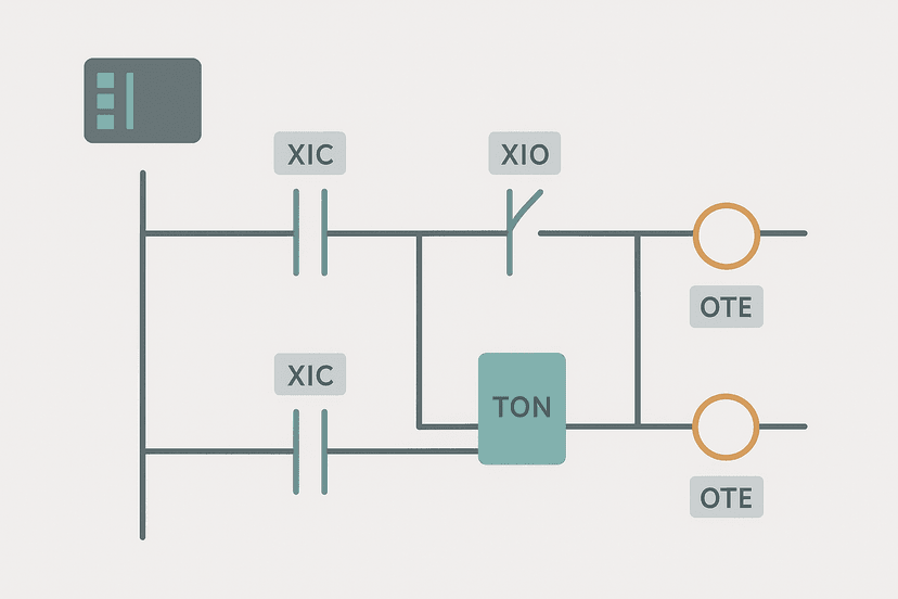
The enable input to the timer is going false before the accumulated value reaches the preset, resetting the accumulator each time. This often happens when the rung enabling the timer has a condition that pulses rather than latches. Check whether any contact on that rung is momentary. A second cause: the preset value is being written from an HMI tag that someone changed to a very large number, so the timer runs but never finishes in the expected time window. Check the preset live in online mode. The TON, TOF and TONR timers post explains accumulator reset behaviour in detail.

11. How would you verify that a safety relay is wired correctly without bypassing the safety function?
Use the safety relay's diagnostics LEDs and status outputs first. Most units have separate indicators for channel 1, channel 2 and cross-fault detection. Then perform a functional test: trigger the E-stop or guard, confirm the safety outputs open, reset and confirm they close again. Measure contact continuity with a multimeter on de-energized circuits only. Never measure a live safety output with a standard continuity tester. The safety relay wiring guide and the emergency stop circuit wiring post both show correct verification procedures.
12. What's the fastest way to determine whether a VFD tripped because of a PLC command or because of a drive internal fault?
Check the drive's fault log first. Every modern VFD logs the fault code, the time, and the operating conditions at the moment of trip. If the fault code is something like overvoltage or overcurrent, the drive tripped on its own. If the drive shows a "run command removed" event, check whether the PLC output dropped or whether the drive's enable input lost power. The VFD fault codes guide lists the common fault codes and their most likely causes across multiple drive families.
13. Describe a real troubleshooting job where you had to think beyond the obvious.
This is a behavioural question disguised as a technical one. The interviewer wants structure and honesty. Use the STAR format loosely: Situation (what the machine was doing), Task (what you needed to find), Action (the specific steps you took, including what you ruled out), Result (what the root cause turned out to be). The best answers include at least one wrong assumption you made, corrected yourself on, and what that taught you. A candidate who claims every diagnosis was obvious the first time is not believable.
14. How do you handle a fault that only occurs once a week and leaves no trace in the PLC diagnostics?
Set up persistent data capture inside the program itself: a counter on the falling edge of the suspect input, a latch bit on any unexpected state transition, or a timestamp written to a FIFO data array when the anomaly occurs. Do not rely on the CPU diagnostics buffer alone since it often overwrites older entries. The intermittent sensor fault troubleshooting post covers exactly this pattern with a counter-latch approach you can copy.
15. What does it mean when an analog input channel shows a "wire break" or "open circuit" fault?
For a 4-20 mA loop, a current below about 3.6 mA is below the valid range and most analog input modules interpret this as a wire break or transmitter failure. The PLC typically sets a channel fault bit and drives the raw count to a defined fail-safe value (often 0 or full scale). Check the loop wiring continuity, then verify the transmitter has loop power. If the loop is intact and the transmitter has power, the transmitter itself may have failed open. The PLC analog input wiring guide covers the loop-powered vs. externally-powered wiring differences that often cause this.
16. How do you distinguish a ground fault from a short circuit in a control panel?
A short circuit is a direct connection between two conductors that should not touch, typically showing as a very low resistance path and often blowing a fuse instantly. A ground fault is an unintended path from a live conductor to earth, which in an isolated 24 VDC system may not blow any fuse but will cause erratic I/O behavior and can be dangerous in AC circuits. Measure insulation resistance to earth with a megger on de-energized circuits. The ground fault finding guide walks through the isolation and segment-by-segment test method.
17. A Siemens S7-1200 is showing a red STOP LED. What are your first three actions?
First: connect TIA Portal and read the diagnostics buffer in the online device view. The buffer gives a specific error code and the time it occurred. Second: check whether the CPU stopped because of a programming error (array out of bounds, type mismatch) or a hardware fault (module failure, power issue). Third: if it's a program fault, identify the offending network using the fault address from the diagnostics buffer, fix the code offline and download. For a first program walk-through on this platform, the S7-1200 first program tutorial explains the project structure and where to find the diagnostic objects.
18. What causes noise on an analog signal and how do you reduce it?
Common sources: VFDs switching at high frequency, inadequate cable shielding, shared conduit with power cables, and a shield grounded at both ends creating a ground loop. For 4-20 mA loops, use shielded twisted-pair cable with the shield grounded at the panel end only. Route analog cables separately from motor and power cables, or at minimum cross them at 90 degrees if they must share a tray. The analog signal cable shielding post and the cable shield grounding guide both cover this with specific distance and grounding recommendations.
19. How do you verify that a PLC program change did not introduce a new hazard?
Use the software's offline compare tool to diff the new version against the approved baseline. Document every changed rung and do a hazard assessment on each change: could this new logic command an output unexpectedly, mask a fault, or defeat an interlock? For safety-critical outputs, re-validate the safety function end-to-end after any program change, regardless of how unrelated the change looks. This is not overkill: I've seen a timer preset change in one routine cause an unrelated safety interlock to bypass because of a shared tag that nobody noticed.
20. What would you check if an EtherNet/IP implicit connection to a drive keeps faulting every few hours?
An implicit connection that faults periodically usually points to a network timeout, not a permanent hardware problem. Check the RPI (Requested Packet Interval) setting: if it is too aggressive for the network load, dropped packets cause a connection timeout. Also check whether any managed switch on the path has spanning-tree enabled without portfast on the device ports, because a spanning-tree topology recalculation can cause a multi-second outage that kills the connection. The EtherNet/IP scanner vs adapter guide explains how connection parameters affect fault behavior.
A Quick Reference: Fault Category Vs. First Tool to Reach For
| Fault Category | First Tool | What You're Looking For |
|---|---|---|
| Digital input wrong state | Multimeter (DC voltage) | Voltage present at terminal vs. sensor state |
| Digital output won't energize | Online ladder monitor then multimeter | Coil state true/false, voltage at terminal |
| Analog reading incorrect | Milliamp clamp or series meter | Actual loop current vs. expected |
| CPU stopped (STOP/fault LED) | Programming software diagnostics buffer | Fault code, time, offending network |
| Comms device offline | Switch port stats, device diagnostics | CRC errors, device name, IP conflict |
| Intermittent fault, no trace | Program-embedded counter/latch rung | Accumulated edge count, latch bit |
How to Structure Any Troubleshooting Answer in an Interview
Interviewers respond well to answers that show a repeatable method. A simple structure that works: State what symptom you observed. List what you ruled out and why, in sequence. Describe the specific test that isolated the root cause. Explain the fix and how you confirmed it worked. That four-step pattern is clear, verifiable and shows you don't just swap parts at random.
If you want more practice on the programming logic side of PLC interviews, the ladder logic interview questions post covers rung analysis, contact logic and common programming traps in the same direct format. And if your interview is for a role that involves Siemens platforms specifically, reviewing TIA Portal data block types and the Structured Text guide for TIA Portal will sharpen your platform-specific knowledge.
What to Read Next
These questions give you the fault-diagnosis framework. Now go deeper on the practical skills behind the answers. Start with PLC troubleshooting using online monitoring to see how the trace and force tools work in a live system. Then work through PLC I/O fault diagnosis with a multimeter to build the hands-on measurement habits that separate competent technicians from guessers. For the programming logic questions you'll also face in interviews, ladder logic interview questions and answers covers the rung-level reasoning interviewers test.
Frequently asked questions
What is the first thing you check when a PLC output won't energize?
What causes a PLC watchdog timeout fault?
How do you troubleshoot a 4-20 mA analog input that reads incorrectly?
What is the difference between a hard fault and a soft fault in a PLC?
How do you find an intermittent input fault without a scope?
What does a flashing I/O module status LED usually mean?
How would you approach a PROFINET communication loss alarm?
What is scan time and why does it matter in troubleshooting?
An output is wired correctly and the coil is true but the device still won't run. What next?
How do you prove a PLC program change caused a new fault?
Now build it
You have just read about TON. Reading a rung and making one behave are different skills, and the second one is the job.
Flasher
Intermediateabout 15 minTwo timers chained in a loop make a lamp blink: the classic two-TON flasher used for warning beacons everywhere. Your first taste of timers driving each other.
Build this rungFree, no signup, runs in your browser. See all 16 exercises.
Was this helpful?