3-Motor Start Sequence PLC Exercise: Ladder Logic
Sequential motor starting is one of the most common control tasks in industrial automation. Conveyors, crushing circuits, ventilation systems, and process lines all start motors in a fixed order to protect electrical infrastructure and mechanical drivetrains. Writing this sequence cleanly in ladder logic, with proper interlocks and fault handling, is a skill every PLC programmer needs to have locked down. This exercise builds it from scratch in Studio 5000, but the pattern transfers directly to any platform.
What Is a Motor Start Sequence in a PLC?
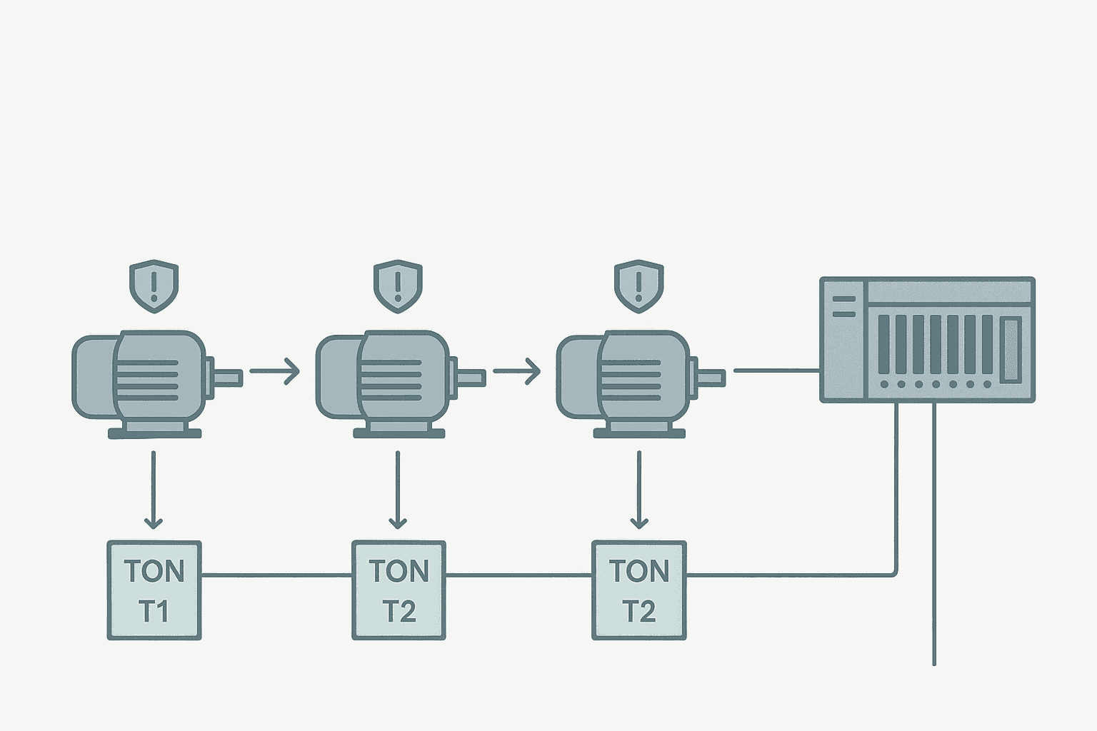
A motor start sequence is a PLC program that commands two or more motors to start in a defined order, with timed delays and run-confirm interlocks between each step. Motor 1 starts first. Once its run-confirm feedback bit goes high and a delay expires, motor 2 starts. The same pattern repeats for motor 3. If any motor fails to confirm within a timeout window, the sequence halts and a fault is raised. No subsequent motor starts until the fault is cleared.
Exercise Specification
Before writing a single rung, define what you are building. Skipping this step is what turns a 30-minute exercise into a two-hour debugging session. Here is the spec for this exercise:
- Three motors: M1 (discharge conveyor), M2 (transfer conveyor), M3 (feed conveyor)
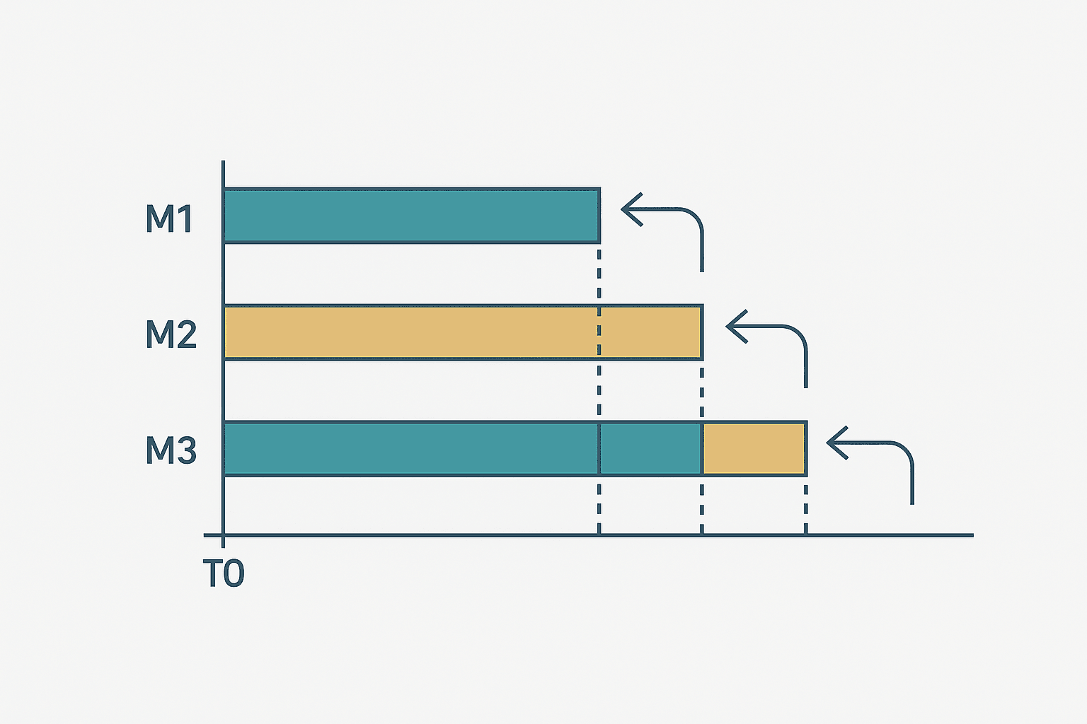
- Start sequence: M1 first, then M2 after a 5-second delay, then M3 after another 5-second delay
- Stop sequence: reverse order (M3 stops first, M2 stops 3 seconds later, M1 stops 3 seconds after M2)
- Each motor has a run-confirm feedback input (contactor auxiliary contact)
- If run-confirm does not arrive within 4 seconds of the output command, latch a fault and halt
- An E-stop clears all outputs immediately with no sequenced stop
- HMI provides Start, Stop, and individual fault-acknowledge bits
I/O Tag List
| Tag Name | Type | Description |
|---|---|---|
| HMI_StartCmd | BOOL Input | Start pushbutton from HMI or panel |
| HMI_StopCmd | BOOL Input | Stop pushbutton from HMI or panel |
| Estop_Active | BOOL Input | E-stop chain open (NC logic, 1 = safe) |
| M1_RunFB | BOOL Input | Motor 1 contactor aux contact |
| M2_RunFB | BOOL Input | Motor 2 contactor aux contact |
| M3_RunFB | BOOL Input | Motor 3 contactor aux contact |
| M1_Out | BOOL Output | Motor 1 contactor coil |
| M2_Out | BOOL Output | Motor 2 contactor coil |
| M3_Out | BOOL Output | Motor 3 contactor coil |
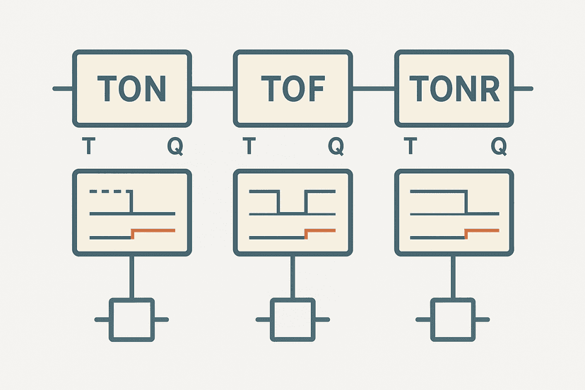
Internal tags you will also need: Seq_Running (BOOL), M1_FaultLatch, M2_FaultLatch, M3_FaultLatch (BOOL), M1_FaultAck, M2_FaultAck, M3_FaultAck (BOOL from HMI), and six TON timer tags: M1_StartTimeout, M2_StartDelay, M2_StartTimeout, M3_StartDelay, M3_StartTimeout, plus M2_StopDelay and M3_StopDelay for the reverse stop sequence. If you are new to timer instructions, the TON, TOF and TONR guide covers the exact instruction behaviour before you wire these up.
Building the Start Sequence Rungs
Rung 1: System Enable (Seq_Running)
The first rung latches the sequence active. A seal-in contact on Seq_Running holds it on after the momentary start button releases. The Stop command and any fault latch break the rung. This is the same pattern covered in the XIC vs XIO contact explanation, and it is the correct way to handle momentary pushbuttons.
3-Motor Timed Start Sequence with Run-Confirm Fault Latches (Studio 5000). Ladder logic (22 rungs): Rung 0: either examine if HMI_StartCmd is on (XIC), or examine if Seq_Running is on (XIC), then examine if HMI_StopCmd is off (XIO), then examine if Estop_Active is off (XIO), then examine if M1_FaultLatch is off (XIO), then examine if M2_FaultLatch is off (XIO), then examine if M3_FaultLatch is off (XIO), then latch output Seq_Running (OTL). Rung 1: examine if HMI_StopCmd is on (XIC), then unlatch output Seq_Running (OTU). Rung 2: examine if Seq_Running is on (XIC), then examine if M1_FaultLatch is off (XIO), then latch output M1_Out (OTL). Rung 3: examine if M1_Out is on (XIC), then examine if M1_RunFB is off (XIO), then TON on M1_StartTimeout. Rung 4: examine if M1_StartTimeout.DN is on (XIC), then examine if M1_RunFB is off (XIO), then examine if M1_Fault_OS is on (XIC), then latch output M1_FaultLatch (OTL). Rung 5: examine if M1_FaultLatch is on (XIC), then examine if M1_FaultAck is on (XIC), then examine if M1_Out is off (XIO), then unlatch output M1_FaultLatch (OTU). Rung 6: examine if M1_Out is on (XIC), then examine if M1_RunFB is on (XIC), then TON on M2_StartDelay. Rung 7: examine if M2_StartDelay.DN is on (XIC), then examine if M2_FaultLatch is off (XIO), then latch output M2_Out (OTL). Rung 8: examine if M2_Out is on (XIC), then examine if M2_RunFB is off (XIO), then TON on M2_StartTimeout. Rung 9: examine if M2_StartTimeout.DN is on (XIC), then examine if M2_RunFB is off (XIO), then examine if M2_Fault_OS is on (XIC), then latch output M2_FaultLatch (OTL). Rung 10: examine if M2_FaultLatch is on (XIC), then examine if M2_FaultAck is on (XIC), then examine if M2_Out is off (XIO), then unlatch output M2_FaultLatch (OTU). Rung 11: examine if M2_Out is on (XIC), then examine if M2_RunFB is on (XIC), then TON on M3_StartDelay. Rung 12: examine if M3_StartDelay.DN is on (XIC), then examine if M3_FaultLatch is off (XIO), then latch output M3_Out (OTL). Rung 13: examine if M3_Out is on (XIC), then examine if M3_RunFB is off (XIO), then TON on M3_StartTimeout. Rung 14: examine if M3_StartTimeout.DN is on (XIC), then examine if M3_RunFB is off (XIO), then examine if M3_Fault_OS is on (XIC), then latch output M3_FaultLatch (OTL). Rung 15: examine if M3_FaultLatch is on (XIC), then examine if M3_FaultAck is on (XIC), then examine if M3_Out is off (XIO), then unlatch output M3_FaultLatch (OTU). Rung 16: examine if HMI_StopCmd is on (XIC), then unlatch output M3_Out (OTU). Rung 17: examine if HMI_StopCmd is on (XIC), then TON on M2_StopDelay. Rung 18: examine if M2_StopDelay.DN is on (XIC), then unlatch output M2_Out (OTU). Rung 19: examine if M2_StopDelay.DN is on (XIC), then TON on M3_StopDelay. Rung 20: examine if M3_StopDelay.DN is on (XIC), then unlatch output M1_Out (OTU). Rung 21: examine if Estop_Active is off (XIO), then unlatch output M1_Out (OTU), then either unlatch output M2_Out (OTU), then either unlatch output M3_Out (OTU). Full 3-motor timed start sequence. M1 starts immediately on Seq_Running. M2 starts 5 s after M1 run-confirm. M3 starts 5 s after M2 run-confirm. Each motor has a 4 s run-confirm timeout that latches a fault and halts the sequence. Stop command reverses order: M3 off first, M2 off after 3 s, M1 off after another 3 s. E-stop clears all outputs instantly.
The diagram above evaluates one scan. Run these exact rungs on a real scan cycle to watch the latching and the timers behave.
Run this in the simulatorHow the Logic Actually Works
Walk through the start path first. When HMI_StartCmd pulses true with no faults active, Seq_Running latches on. The next rung immediately sets M1_Out. The timeout timer M1_StartTimeout starts ticking the moment M1_Out is on and M1_RunFB is still off. If the contactor closes within 4 seconds, M1_RunFB goes true, the timer rung goes false, and the timer stops without reaching DN. No fault. The delay timer M2_StartDelay then starts, gated by M1_Out AND M1_RunFB. After 5 seconds, M2_Out latches on and the same pattern repeats for motor 2, then motor 3.
The fault path is what separates a production program from a textbook example. If M1_RunFB never arrives and M1_StartTimeout.DN goes true, a one-shot (OSR) fires exactly once and latches M1_FaultLatch. That latch immediately breaks the Seq_Running enabling rung, so no further motors can start. The operator has to acknowledge the fault from the HMI (with the machine stopped) before the latch clears. This one-shot pattern is important: without it, the fault latch would continuously try to set and clear on every scan. The OSR and edge detection approach is worth reviewing if this is new to you.
Seq_Running. Gate it only with the motor output and the absence of run-confirm. If you gate it with Seq_Running, a stop command resets the timer before DN fires, masking the fault on short stop-start cycles. I saw this exact bug cause an undetected failing contactor on a flour mill conveyor. It ran for weeks dropping product before someone noticed.The Reverse Stop Sequence
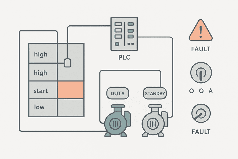
A clean stop matters as much as a clean start. When HMI_StopCmd fires, M3_Out is immediately unlatched (feed conveyor stops, no more material entering the line). M2_StopDelay starts timing. After 3 seconds, M2_Out unlatches. M3_StopDelay then starts, and after another 3 seconds M1_Out unlatches. The discharge conveyor runs last, clearing whatever is still on the belt. This is exactly the same principle used in the pump station exercise, just applied to a conveyor train instead of a wet well.
The E-stop path is separate and unconditional. A single rung with XIO(Estop_Active) fires three OTU instructions in one scan. No delay, no sequence. Safety hardware handles the physical disconnection; the PLC just mirrors that state in software immediately. For more on how the E-stop circuit itself is wired, see emergency stop circuit wiring categories.
Common Mistakes in Motor Sequence Logic
- Using OTE instead of OTL/OTU for motor outputs: the output drops for one scan whenever a seal-in rung momentarily goes false, which can cause contactors to chatter.
- Forgetting to reset the delay timers when the sequence stops: if you restart quickly, the delay timer still has its accumulated value and M2 or M3 may start instantly on the next run.
- Setting run-confirm timeout too short: 4 seconds is fine for a direct-on-line motor under 5.5 kW, but a larger motor through a star-delta starter may need 8 to 12 seconds to fully confirm.
- Not including any fault in the Seq_Running guard: if M2 faults and M1 is still running, you need to decide whether M1 should coast or stop. Feeding
Seq_Runningthrough all fault latches forces a deliberate choice. - Wiring a normally-closed auxiliary contact as the run-confirm: if the contact wires break, the PLC sees false run-confirm permanently, masking real faults. Use NO auxiliary contacts for run-confirm and let the timeout catch open-circuit failures.
Extending the Exercise
Once the base sequence works, add these layers to make it production-grade:
- Add a CTU counter that counts successful start cycles. After 500 cycles, set a maintenance-due bit. See PLC counter instructions for the CTU setup.
- Add an HMI faceplate showing each motor's state: stopped, starting, running, faulted. The HMI tag linking guide shows how to map these bits correctly.
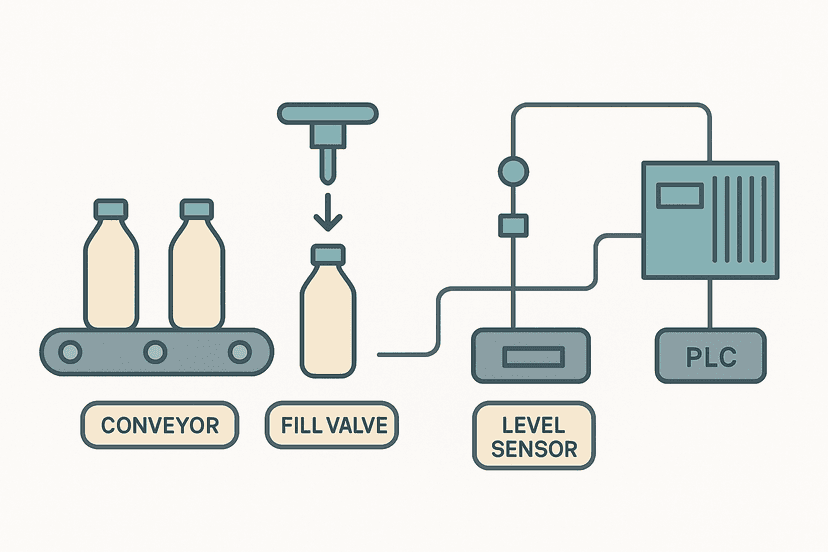
- Replace the fixed 5-second inter-motor delay with an HMI-adjustable DINT parameter loaded from a recipe. This is the same indexed recipe pattern used in the bottle filling project.
- Add a 'jog' mode that allows individual motor starts without the sequence, gated by a key switch input so operators cannot accidentally jog a motor mid-production.
- Test the fault path deliberately: with the program running in simulation (see how to simulate ladder logic without a PLC), force
M2_RunFBto stay false and confirm the fault latches, M3 never starts, and the ack cycle works correctly.
Translating This to Siemens TIA Portal
The structure maps cleanly to S7-1200 or S7-1500. Replace OTL/OTU with Set/Reset coils (S and R). Replace Rockwell TON with the IEC TON function block from the standard library. Tag names follow the TIA Portal convention (e.g., M1_StartTimeout.Q instead of .DN). If you are new to TIA Portal timers, S7-1200 timers in TIA Portal covers the exact block interface. The fault latch OSR pattern works the same way using a P_TRIG coil instead of an OSR instruction. Store the fault bits in a Global DB for clean HMI access, as shown in the S7-1200 Global vs Instance DB guide.
Troubleshooting the Sequence Online
Once the program is downloaded, use online monitoring to step through the sequence in real time. Watch the timer accumulated values climb and confirm each DN bit fires at the right moment. If M2_StartDelay never starts timing, check that M1_RunFB is actually going true: force the input in software (with the machine safe and isolated) and confirm the rung logic. The PLC troubleshooting with online monitoring guide has a systematic method for exactly this kind of step-by-step verification. If a physical input is suspect, how to test a PLC input with a multimeter will confirm whether the signal is reaching the module at all.
What to Read Next
The motor start sequence is a core building block. From here, take on the PLC pump station exercise which adds duty/standby alternation and high-level interlocks to a similar timed structure. For a more complex sequential machine, the PLC bottle filling machine project introduces step-based state control that scales to larger systems. And if you want to sharpen your troubleshooting skills on sequences like this one, work through the PLC troubleshooting interview questions to see how faults in sequential logic are diagnosed under pressure.
Frequently asked questions
What is a motor start sequence in a PLC?
Why use timed delays between motor starts?
What happens if a motor does not reach run speed in time?
How do I stop all three motors safely in the right order?
Can I use this exercise on a Siemens S7-1200 instead of Rockwell?
What inputs and outputs do I need for this exercise?
Should I use OTE or OTL/OTU for the motor output coils?
How long should the inter-motor delay be?
Is this exercise suitable for a beginner?
Now build it
You have just read about OTU and XIO and OTL. Reading a rung and making one behave are different skills, and the second one is the job.
State Coil / Fault Coil
Intermediateabout 15 minA fault lamp that latches ON when any alarm condition occurs, even briefly, and only clears on Reset. And if the condition is still present when Reset is released, the fault comes right back.
Build this rungFree, no signup, runs in your browser. See all 16 exercises.
Was this helpful?